


E-6
English
Connections
GETTING STARTED
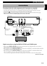
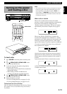
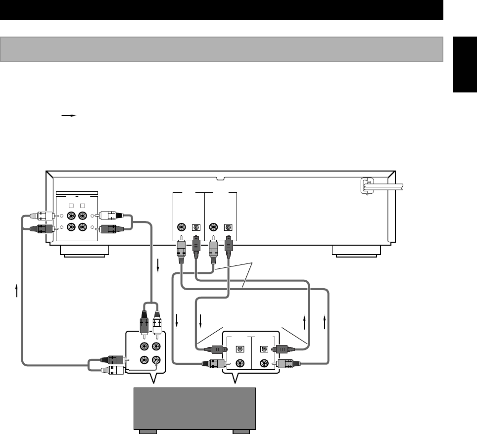
Digital connections using the DIGITAL OPTICAL and COAXIAL jacks
• Before using the DIGITAL OPTICAL jacks, be sure to remove the jack covers. Replace the jack covers in order to
protect the jacks from dust when they are not being used.
• Make connections from the DIGITAL OPTICAL jacks on this unit to the “MD/DAT” (or equivalent) digital optical jacks
on an amplifier or receiver by using optical fiber cables.
• Make connections from the DIGITAL COAXIAL jacks on this unit to the “MD/DAT” (or equivalent) digital coaxial
jacks on an amplifier or receiver by using commercially available coaxial cables.
* Do not connect the digital audio coaxial cable to analog line jacks. If connection is made, noise will be produced.
Do not plug in this unit or other components until all connections are completed.
• Connections should be made to the correct input and output jacks of the amplifier or other components.
• To record a wider variety of sources, it is recommended to make both analog and digital connections to this unit.
• Arrow marks (
) in the illustration below indicate the direction of the audio signal.
• Guidelines for making both analog and digital connections to this unit are outlined on this and the following page.
• When all connections are complete, plug in this unit to a wall outlet.
ANALOG
LINE IN
REC
4
L
PLAY
3
LINE OUT
R
L
R
DIGITAL IN
COAXIAL OPTICAL
DIGITAL OUT
COAXIAL OPTICAL
MD/DAT
MD/
DAT
MD/
DAT
PLAY
RL
REC
DIGITAL IN DIGITAL OUT
OPTICAL OPTICAL
COAXIAL COAXIAL
To wall
outlet
Amplifier or Receiver
RCA pin cable
(included)
<CDR-S1000>
RCA pin cable
(included)
Optical fiber cables
(one included)
Coaxial cables
(not included)
Continued on next page