


En 121
■ Display Set
Configures the settings related to the front display and TV screen display.
❑ Front Panel Display
Configures the front display settings.
Dimmer
Adjusts the brightness of the front display.
Setting range
-4 ~ 0 (higher to brighten)
Default
0
Scroll
Sets the scrolling manner of the front display.
The display scrolls automatically if the text exceeds 14 characters.
Settings
❑ Short Message
Selects whether to display short messages on the TV screen when this unit is operated
(input selection, volume adjustment, etc).
Settings
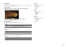
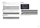
❑ Wall Paper
Selects a wall paper displayed on the TV.
Settings
■ Trigger Output1, Trigger Output2
Sets the TRIGGER OUT 1~2 jacks to function synchronized with power status of each
zone or input switching.
❑ Trigger Mode
Specifies the condition for the TRIGGER OUT jack to function.
Settings
❑ Target Zone
Specifies the zone with which the TRIGGER OUT jack functions synchronized.
Settings
Continue (default) Sets the display to scroll continuously.
Once
Sets the display to scroll all characters once and then halt scrolling for
display of the first 14 characters.
On (default) Displays short messages on the TV screen.
Off Does not display short messages on the TV screen.
Picture1, Picture2, Picture3
Displays the selected image on the TV screen when there
is no video signal.
Gray
Displays a gray background on the TV screen when there
is no video signal.
Power (default)
The TRIGGER OUT jack functions synchronized with the power status of the zone
specified with “Target Zone.”
Source
The TRIGGER OUT jack functions synchronized with the input switching in
the zone specified with “Target Zone.”
Electronic signal is transmitted according to the setting made in “Target
Source.”
Manual
Select this to manually switch the output level for electronic signal transmission with
“Manual.”
Main
When “Trigger Mode” is set to “Power,” electronic signal transmission is
synchronized with power status of the main zone.
When “Trigger Mode” is set to “Source,” electronic signal transmission is
synchronized with input switching in the main zone.
Zone2
When “Trigger Mode” is set to “Power,” electronic signal transmission is
synchronized with power status of Zone2.
When “Trigger Mode” is set to “Source,” electronic signal transmission is
synchronized with input switching in Zone2.
Zone3
When “Trigger Mode” is set to “Power,” electronic signal transmission is
synchronized with power status of Zone3.
When “Trigger Mode” is set to “Source,” electronic signal transmission is
synchronized with input switching in Zone3.
All (default)
When “Trigger Mode” is set to “Power,” electronic signal transmission is
synchronized with power status of the main zone, Zone2 or Zone3.
When “Trigger Mode” is set to “Source,” electronic signal transmission is
synchronized with input switching in the main zone, Zone2 or Zone3.