61
12. UTILITY SETTINGS
UTILITY
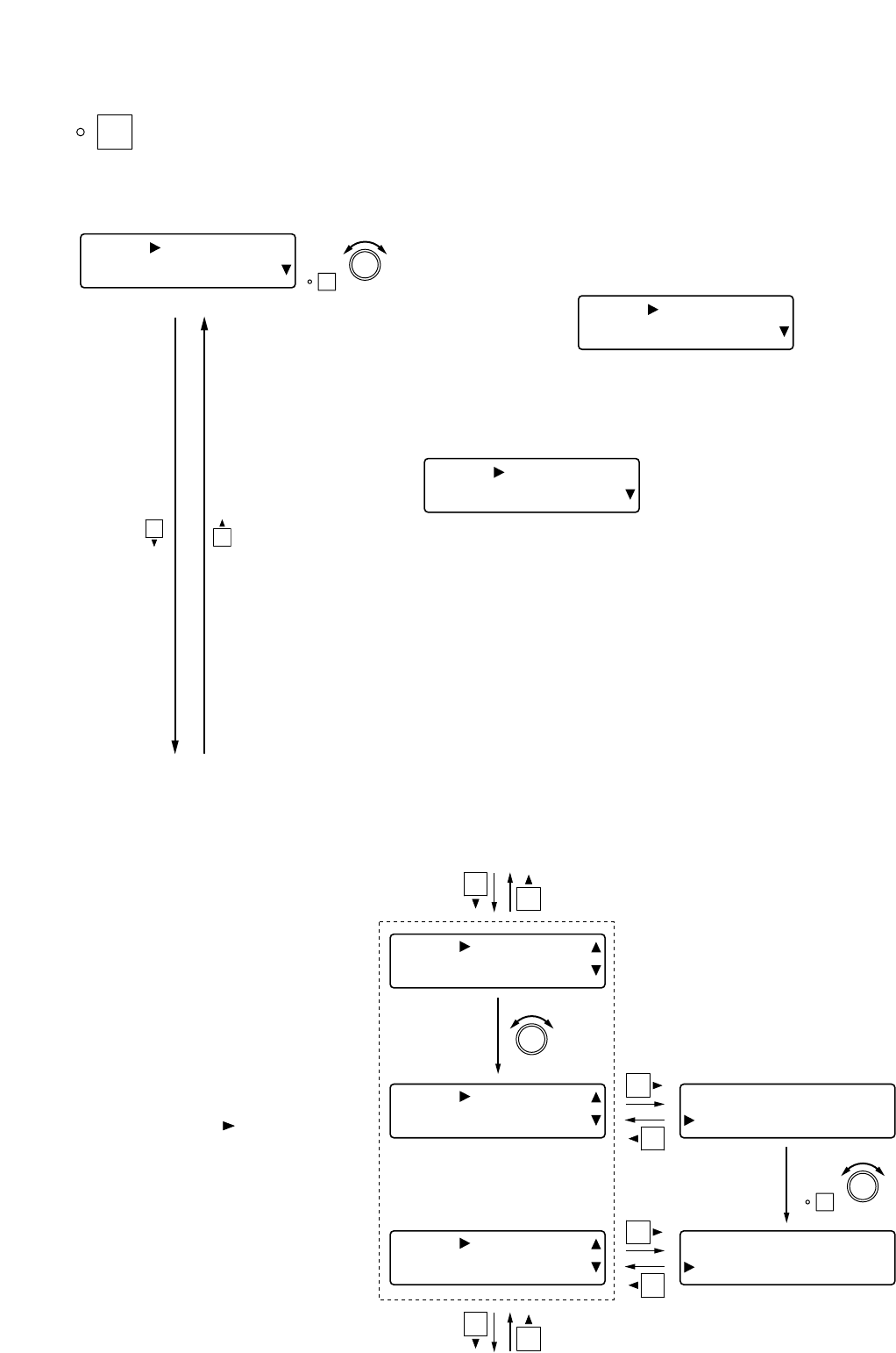
The utility setting screen is displayed when the Utility key is pressed.
12.1. Stereo Link Settings
[UTY] STR LINK
[IN 1 ] [IN 2
]
ON
PARAMETER
PUSH-ENTER
CHANGE
• Rotate the Setting knob to select the channels to be "Stereo-
Linked."
• Press the function ON/OFF key to enable or disable the Stereo-
Link setting.
[Setting example]
12.2. Group Settings
By grouping multiple channels
together, the gains of these channels
can be simultaneously adjusted using
the Input or Output volume control.
[ UTY ] GROUP I NG
[IN 1
]
[IN 3]––3 –––
IN 1] –––––
–
[ UTY ] GROUP I NG
[IN 3]
[ UTY ] GROUP I NG
[ I N 3 ] 3
4
[IN 3]––34––
IN 4] ––––––
ON
Stereo Link setting (above item)
Crossover configuration (high frequency) settings (next page)
PARAMETER
PUSH-ENTER
CHANGE
PARAMETER
PUSH-ENTER
CHANGE
4
3
2
1
Step 1. Rotate the Setting knob to
display the channels to be
grouped in the [ ] area on
the lower row.
Step 2. Press the shift key.
[UTY] STR LINK
[IN 1 ]=[IN 2]O
N
[UTY] STR LINK
[OUT1 ]x[OUT2]–
–
• The following "Stereo-Linked" channel parameter settings are
synchronized:
Input channel: PAD, Phantom power, Input trim gain, High-pass
filter, Parametric equalizer, Compressor/auto-
leveler*, Gate*, Auto-mixing group, Ducker, NOM
attenuation ON/OFF, Input channel gain,
Channel ON/OFF, and Group settings
Output channel: Output channel gain, Filters 1 – 6 (including
crossover), Compressor*, Delay, and Group settings
* Operations are also synchronized.
Tip
When the input channel and the output channel are both set for
Stereo Link, the bus assignment setting is also synchronized.
(Refer to p. 41.)
Note
The output channel that is enabled for crossover function - a
parameter except "NONE" is set - in the Crossover Configuration
Settings (p. 62) is displayed on the screen as follows, not being
set as a "Stereo-Linked" channel.


