43
9.3. Crossover Settings (Only when Crossover function is enabled)
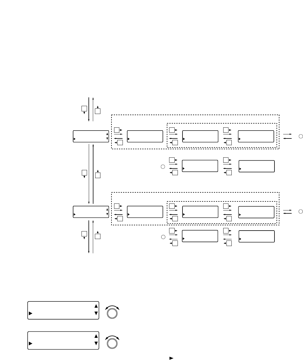
The following screens are displayed only when the crossover function is enabled on the Utility setting screen.
(Refer to p. 62 for more information.)
[OUT1] XOVER-HF
TYPE THR
U
[OUT1] XOVER-HF
FREQ 1 .00kHz
[OUT1] XOVER-HF
Q 0.500
[OUT1] XOVER-LF
TYPE THR
U
[OUT1] XOVER-LF
FREQ 1 .00kHz
[OUT1] XOVER-LF
Q 0.500
[OUT1] XOVER-LF
Q2 0 .50
0
(High frequency)
(Low frequency)
(Displayed when parameters other than THRU are selected)
(Displayed depending on the type of slope)
(Displayed depending on the type of slope)
(Displayed when parameters other than THRU are selected)
To A
To B
A
B
Slope Cutoff frequency Q
[OUT1] XOVER-HF
Q2 0 .50
0
Q2
Crossover gain
Crossover filter polarity
Output channel gain settings
(previous page) or
Output channel group trim
gain settings (previous page)
Filter settings (p. 45)
[OUT1] XOVER-HF
POL NORMA
L
[OUT1] XOVER-LF
GA IN +0 . 0d
B
[OUT1] XOVER-LF
POL NORMA
L
[OUT1] XOVER-HF
GA IN +0 . 0d
B
[Screen display operations]
9.3.1. Slope settings
[OUT1 ] XOVER- HF
TYPE THR
U
[OUT1 ] XOVER- LF
TYPE THR
U
(Low frequency)
(High frequency)
PARAMETER
PUSH-ENTER
CHANGE
PARAMETER
PUSH-ENTER
CHANGE
• Rotate the Setting knob to select the type of slope.
Parameter setting range: THRU (through), 6 dB (6 dB/oct), 12BS
(12 dB/oct BS), etc. (Refer to p. 87 for
more information.)
Notes
(1) Slope type: BS (Bessel), BW (Butterworth), LR (Linkwitz-
Riley), VQ (Variable Q)
(2) Displayed slope type differs depending on the Crossover
configuration setting. (Refer to p. 62.)
• Using the shift key, the display is moved to the Crossover
Gain setting screen if THRU is selected, and to the Cutoff
Frequency setting screen if parameters other than THRU are set.
• Pressing an Output channel selector key permits the crossover
filter to be set for that channel. The [OUT 1] indication changes to
the selected channel number indication.


