


30
The final example of digital
modulation spreads the energy
in a BPSK signal by amplitude
modulating the carrier with a
spreading pattern. In the same
way that the baseband data
pattern spreads the energy of an
unmodulated carrier, a spread-
ing pattern further spreads the
energy of a modulated carrier.
Pseudo-random sequences are
generally used as the spreading
pattern, with a bit rate or chip-
ping rate that is much higher
than the data bit rate. The
511-bit pseudo-random
sequence generated in Figure 25
is used as the spreading
sequence—the assumption being
that a receiver would use the
same sequence to de-spread the
signal. Since the data pattern is
28 bits, one can directly imple-
ment a chipping rate to data rate
ratio of 18.25 or (power reduc-
tion of 12.6 dB) by simply
mapping the 511-bit sequence
into 28,000 AWG record points.
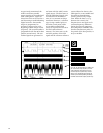
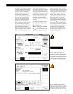
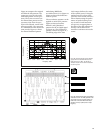
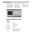
Figure 40 shows how the AWG’s
waveform editor can horizontally
interpolate a waveform into
another record size. The spread-
ing is implemented by using the
AWG waveform editor to multi-
ply the spreading sequence and
the modulated BPSK carrier
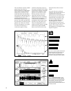
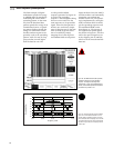
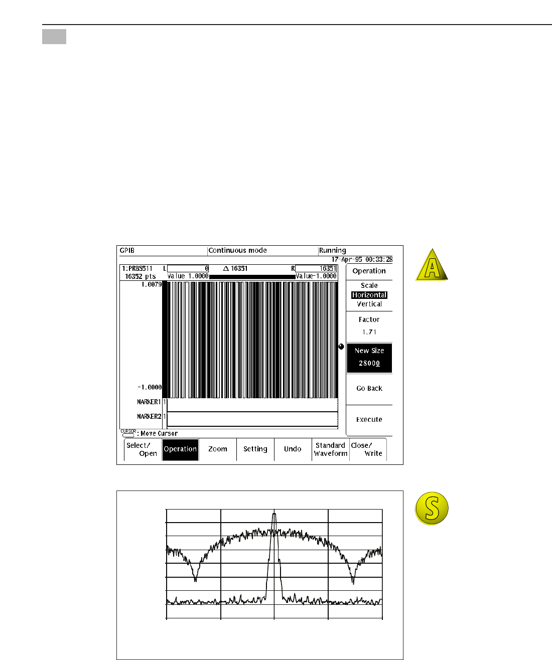
from Figure 37. The spectra of
the original and spread signals
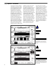
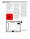
are shown in Figure 41. The first
null in the spread signal occurs
at the chipping rate of 730 kHz,
which is 18.25 times the 40 kHz
data rate.
Figure 40. The AWG waveform editor performs
horizontal scaling of the 511-bit spreading
sequence. The original record length was
16,352 points. A “new” size of 28,000 points is
entered, and the AWG expands and interpolates
the waveform by a factor of 1.71.
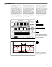
Frequency (kHz
-80
-70
-60
-50
-40
-30
-20
-10
0
9700 10200 10700 11200 11700
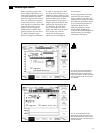
Figure 41. Spectrum analyzer plots of the BPSK
carrier at 10.7 MHz before and after a 511-bit
pseudo-random spreading sequence. The data
rate is 40 kbaud and the chipping rate is 730 kHz.
The original spectrum is the same as the filtered
spectrum in Figure 38, but it is displayed here at
a wider span.
Direct Sequence Spread Spectrum
14
Magnitude (dBm)