


23
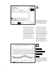
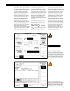
The modulating data alters the
carrier frequency in
frequency-shift keying (FSK). A
digital modulation index of 0.5
is used in this example; that is,
the frequency shift will be
1
⁄2 the
40 kbaud data rate or 20 kHz. If
the carrier remains centered at
10.7 MHz, this results in the two
data frequencies of 10.710 MHz
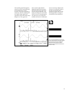
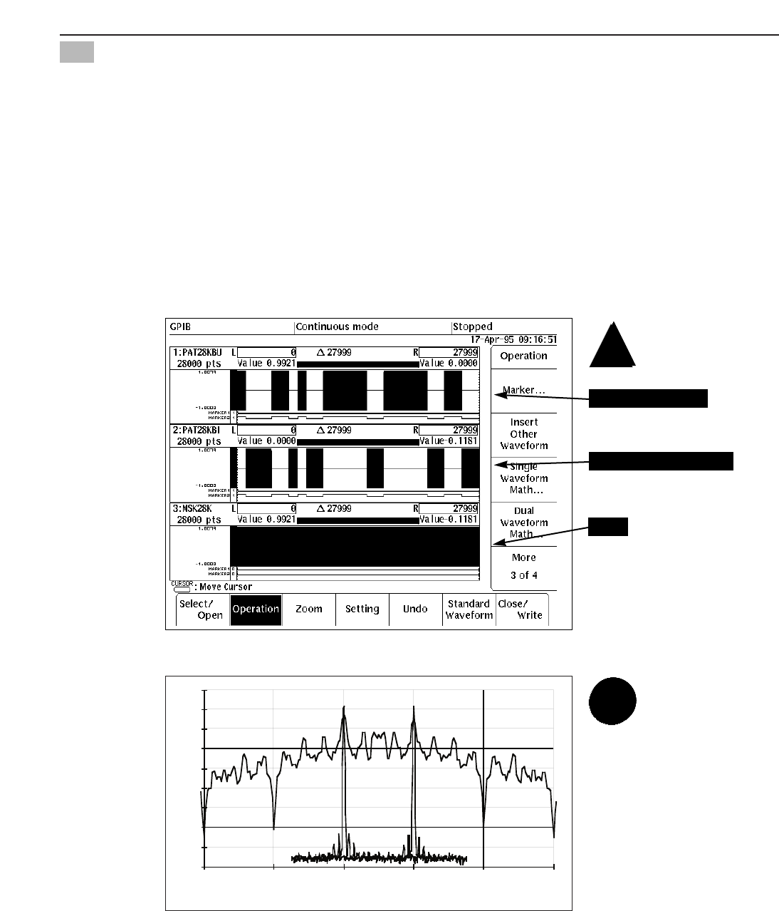
and 10.690 MHz. Figure 28
shows one way to implement
binary FSK to take advantage of
the AWG’s mathematical preci-
sion. First, a second 28-bit data
pattern is generated which is the
1’s complement of the original
pattern. Then two 28,000 point
carriers are generated at
10.690 MHz and 10.710 MHz.
Note that the carriers are phase
continuous since exactly 7483
and 7497 cycles, respectively, of
the carriers fit in the 700 µs
record. The upper waveform is
the 10.690 MHz carrier
multiplied by the original data
pattern, and the middle wave-
form is the 10.710 MHz carrier
multiplied by the complemented
pattern. If the two waveforms are
added (bottom trace), then the
carrier shifts between the two
frequencies exactly at the data
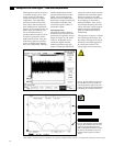
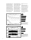
transitions. The spectra of the
two unmodulated carriers and
the modulated FSK signal are
shown in Figure 29.
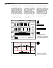
Figure 28. FSK: Upper waveform is the
10.690 MHz carrier amplitude modulated by the
data pattern. Middle waveform is the 10.710 MHz
carrier modulated by the complemented pattern.
The sum of the two waveforms shifts between the
two frequencies at data transitions.
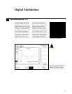
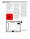
Frequency (kHz
-90
-80
-70
-60
-50
-40
-30
-20
-10
0
10650 10670 10690 10710 10730 10750
Figure 29. Spectrum analyzer plots of the two
unmodulated carriers, at 10.690 MHz and
10.710 MHz, and an overlay of the FSK signal
with the 28-bit modulation.
Digital FM — FSK
11
Sum
Carrier x data pattern
Carrier x data complement