


21
Baseband Digital Patterns
9
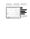
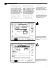
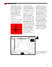
Before continuing with exam-
ples of digital modulation, it is
important to establish a method
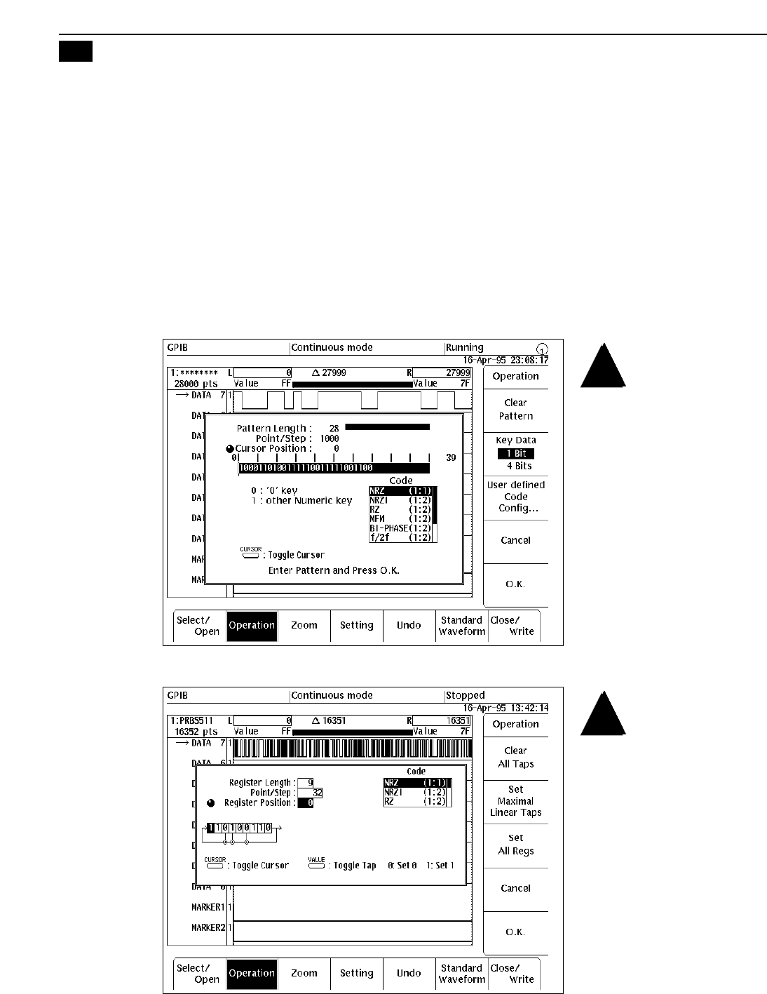
of creating arbitrary test data
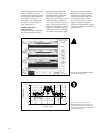
patterns. Figure 24 shows direct
entry of a 28-bit binary pattern.
In this case, the 0 or 1 value of
each data bit is repeated for 1000
points in the record, which
requires a record length of
28,000 points. A binary data
pattern requires only one bit of
the AWG’s dynamic range.
Multi-level digital encoding can
be used by altering more than
one bit at each record point. In
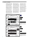
addition to direct data entry, the
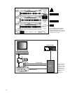
AWG can automatically generate
pseudo-random data streams.
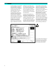
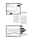
Figure 25 shows the setup for a
length = 9 linear feedback shift
register that repeats only after
511 data bits. As with direct
entry, the number of record
points per data bit can be speci-
fied. In this case, each bit
repeats for 32 data points,
requiring a record length of
16,352 points.
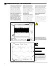
In some applications, the data
pattern itself is the desired
output signal for the AWG. For
example, the data pattern can be
the baseband modulation signal
to an external RF generator or
modulator. However, the
following examples use the
simple 28-bit, 28,000 point
record as the baseband signal in
demonstrating several digital
modulation techniques.
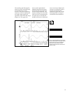
Figure 24. A binary or hex (4-bit) data pattern
can be directly entered from the keypad. The
AWG directly translates a variety of encoding
formats such as NRZ, RZ, and NRZI. The number
of record points that each bit interval occupies
can be specified.
Figure 25. The pseudo-random generator
supports register lengths from 2 to 32 bits. The
binary output stream from the generator can be
assigned to a specific bit in the output range or to
one of the marker bits.