


19
Digital Phase Modulation — PSK
8
The modulating signals in the
foregoing examples have been
sinusoidal or continuous wave-
forms. A simple step to digital
modulation is made with a slight
variation to sinusoidal modula-
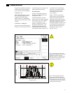
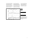
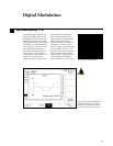
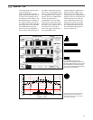
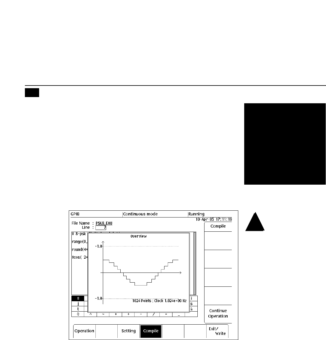
tion. Figure 21 shows one cycle
of a sinewave that has been
quantized into steps between
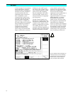
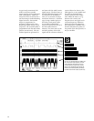
–0.5 and +0.5. The equation
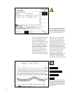
defining these steps is shown in
Figure 22. The second line
simply quantizes a cosine wave
by rounding and scaling the
continuous waveform to the
nearest eighth. This quantized
modulating pattern is then
directly inserted in the phase
argument of a cosine carrier.
Thus, the phase argument takes
on values between –π to +π in
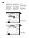
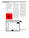
π/4 steps. If the polar graphical
representation of the signal is
used, a family of eight points of
equal magnitude is defined,
spaced around the circle in π/4
or 45° phase increments.
Figure 21. The sinusoidal modulating pattern is
quantized into discrete steps. The steps are
equally spaced in amplitude and will shift the
phase of the carrier in π/4 or 45° increments.
Digital Modulation