


27
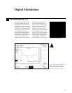
One effect of the edge transitions
in digital modulation patterns is
a wider than desired occupied
spectrum of the transmitted
signal. The solution is to filter
the baseband digital signal
before it modulates the carrier.
The two most common filter
types for this application are
Gaussian and Nyquist filters.
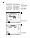
Application of the Gaussian
filter is illustrated here, though
the process for applying any
filter type is the same. The base-
band modulating pattern is
filtered by convolving it with the
impulse response of the desired
filter in the time-domain. The
AWG directly performs the
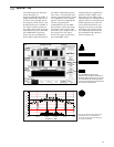
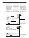
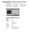
convolution function. Figure 34
shows the convolution setup.
The upper left waveform is the
28,000 point data pattern, while
the lower left waveform is the
2000 point Gaussian impulse
response. The result of the
convolution process is shown at
the right.
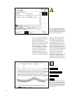
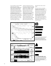
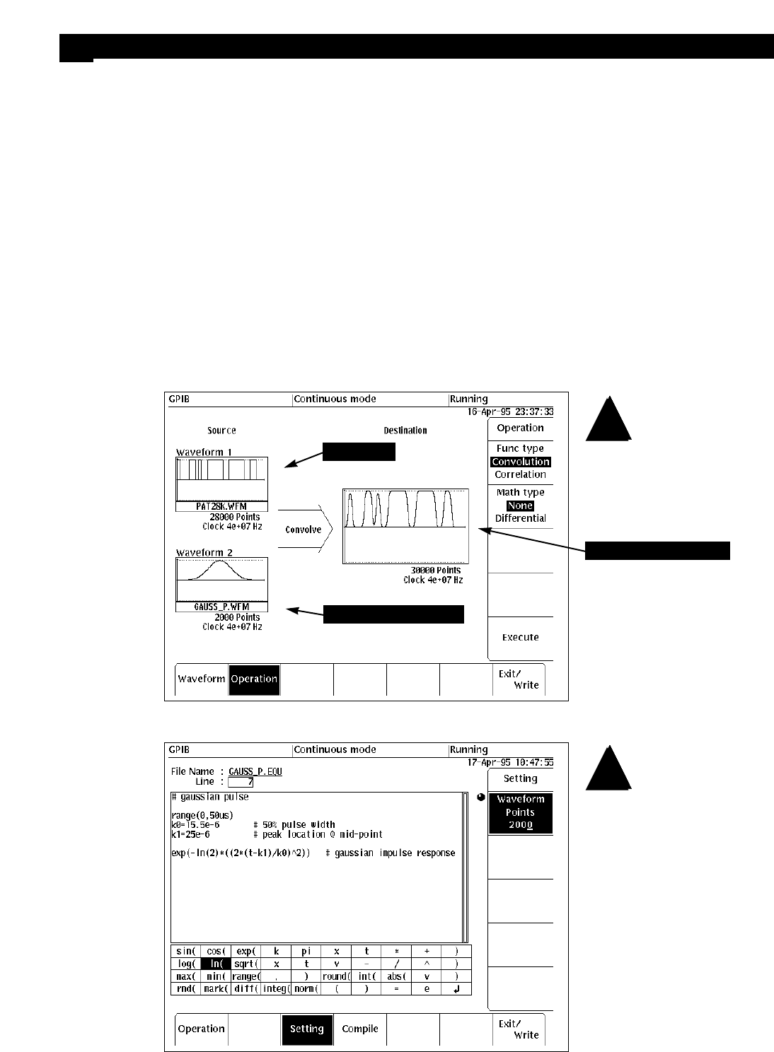
The impulse response of the
Gaussian filter is defined by:
h(t) = exp {–t
2
/2s
2
},
where s = PW
50
/(2 √(2 ln(2)).
PW
50
is the half-width for the
pulse and is approximately
equal to 0.31/B, where B is the
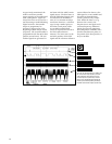
filter bandwidth in Hz. Figure 35
shows the implementation in the
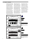
AWG’s equation editor. The key
parameter to select is the half-
width. This example uses a BT
parameter of 0.5, where B is the
filter bandwidth and T is the
data period (25 µs). This means
the bandwidth must be 20 kHz
and the PW
50
= 15.5 µs. By trial
and error it is determined that a
50 µs total pulse interval defines
the total response so that both
tails drop to zero within the
interval. For the sample rate of
40 MHz, this requires a record
length of 2000 points.
Figure 34. The data pattern (upper left) is
convolved with the Gaussian impulse response
(lower left). The result is the filtered data pattern.
The convolution of the two waveforms produces a
new waveform that is 30,000 points long. This is
the sum of the two individual waveform lengths
and is a by-product of the convolution process.
Figure 35. The Gaussian impulse response is
defined by the pulse half-width, which is approxi-
mately equal to 0.31/B, where B is the –3 dB filter
bandwidth. The constant k1 offsets the peak of
the impulse response to the center of the record.
Filtering Out Unwanted Sidebands
13
Data pattern
Gaussian impulse response
Resulting convolved signal