


25
Multi-level data modulation
splits the amplitude, frequency,
or phase of the carrier into more
than two discrete states. 8-PSK
previously demonstrated direct
control of the phase Φ in the
equation A cos(ω
c
t + Φ); A was
constant. The eight symbols
were equally spaced points
around the polar axes.
Alternatively, the I-Q mapping
can be used by noting the
relationship:
A cos(ω
c
t + Φ)
= A cos Φ cos(ω
c
t) – A sin Φ sin(ω
c
t)
That is, any symbol location can
be expressed as a vector sum of
an in-phase (I) component and
an orthogonal quadrature
component (Q). Thus, if we
select 16 equally spaced points
to send 4 bits of information per
symbol, then we can easily
transmit the symbols by ampli-
tude modulation of two carriers.
For example, the I component
could be –
3
⁄4, –
1
⁄4,
1
⁄4, or
3
⁄4 times
cos(ω
c
t). The Q component
would be one of the same
multipliers applied to sin(ω
c
t).
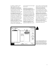
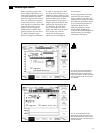
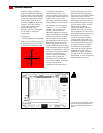
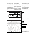
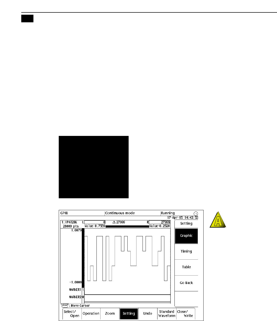
Figure 31 illustrates a 28-symbol
pattern, each with one of these
four multipliers. Each quadra-
ture component carries 2 bits of
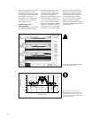
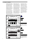
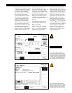
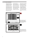
information. Figure 32, on the
following page, illustrates the
creation of the quadrature ampli-
tude modulated carrier using the
AWG’s waveform editor. The top
waveform is the I pattern modu-
lating the 10.7 MHz cosine
carrier. A separate 28-symbol
Q pattern was created and
modulates the 10.7 MHz sine
carrier in the middle waveform.
The two waveforms are
combined in the third pattern.
Signal impairments are easily
generated with this approach.
The cosine or sine carrier (before
modulation) can be altered
relative to each other in phase or
amplitude to simulate errors in
the modulated signal. For exam-
ple, the cosine carrier could be
altered from cos(ω
c
t) to
cos(ω
c
t+δ) where δ is a small
offset to move the two carriers
out of quadrature. Or the levels
of the baseband data pattern can
be altered in the waveform
editor to corrupt the uniform
spacing of the 16 symbols. To
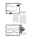
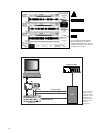
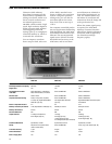
accomplish quadrature modula-
tion at appropriate frequencies,
it may be necessary to couple
the AWG with a specialized
dual-input RF signal generator
designed to handle I and Q
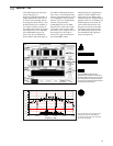
information. Figure 33 depicts
the interconnection of the two
instruments, as well as the other
elements of the test setup.
Figure 31. The AWG’s waveform editor was used
to generate this 28-symbol data pattern which
has four potential uniformly spaced levels per
symbol.
Quadrature Modulation
12