


14
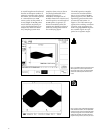
A final example of conventional
analog modulation combines
most of the above techniques to
simulate the stereo modulation
used in broadcast FM. The
modulating signal consists of
three components, 1) the
composite audio which is the
sum of the left and right (L+R)
channels, 2) the stereo pilot
signal which is a 19 kHz tone,
and 3) the difference (L-R) signal
which amplitude modulates a
38 kHz carrier. These three
components are summed
together and modulate the
carrier using conventional FM.
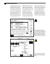
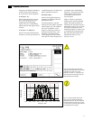
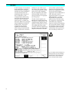
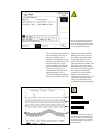
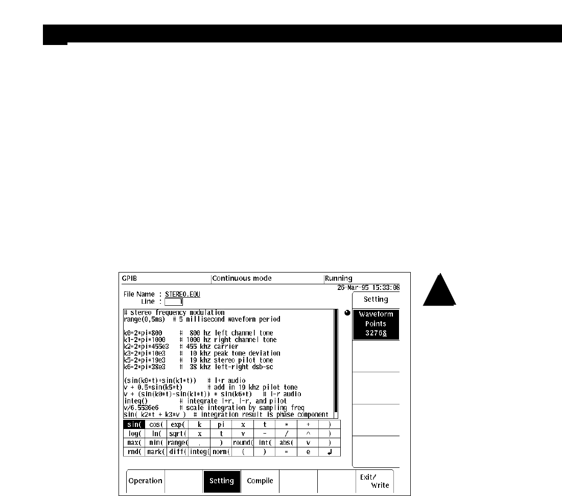
Figure 14 shows the waveform
definition in the AWG’s equa-
tion editor. This example uses a
5 ms waveform period, a 32768
point record, and a sampling
rate of 6.5536 MHz. The carrier
will be 455 kHz, which can be
mixed externally to an appropri-
ate IF frequency.
The left channel signal is an
800 Hz tone and the right chan-
nel signal is a 1000 Hz tone. The
composite audio signal (L+R) is
made by summing the two tones.
The 19 kHz pilot tone is then
summed at half the amplitude of
the audio tones. The (L-R) signal
amplitude modulates a 38 kHz
carrier which is phase-locked
(implicit in the equation defini-
tion) to the 19 kHz pilot. Unlike
the previous AM example,
suppressed carrier modulation is
used, where the carrier is
suppressed if there is no modu-
lating signal (the “1” term is
absent from the modulation
product term). The three terms
are integrated to implement FM
modulation; the integration
output is scaled by the sampling
rate as described earlier. Finally,
the integrator output is inserted
into the phase term of the sinu-
soidal carrier with a peak devia-
tion of 10 kHz per audio tone.
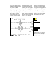
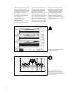
FM Stereo
6
Figure 14. Definition of the stereo FM signal. The
waveform period was 5 ms. All the modulating
components have an integer number of cycles
within the record (i.e., they are multiples of
200 Hz) so the signal is phase continuous.