


20
The record length of 1024 points
and a waveform period of 1 µs
requires a sampling rate of
1.024 GHz. The resulting carrier
frequency is 50 MHz. Since each
level represents one of eight
states or symbols, 3-bits of data
can be transmitted per symbol.
Of course, no data per se is
associated with this particular
modulating pattern since a
sinusoid was quantized without
regard to the symbol or baud rate.
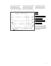
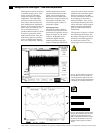
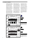
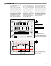
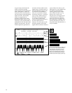
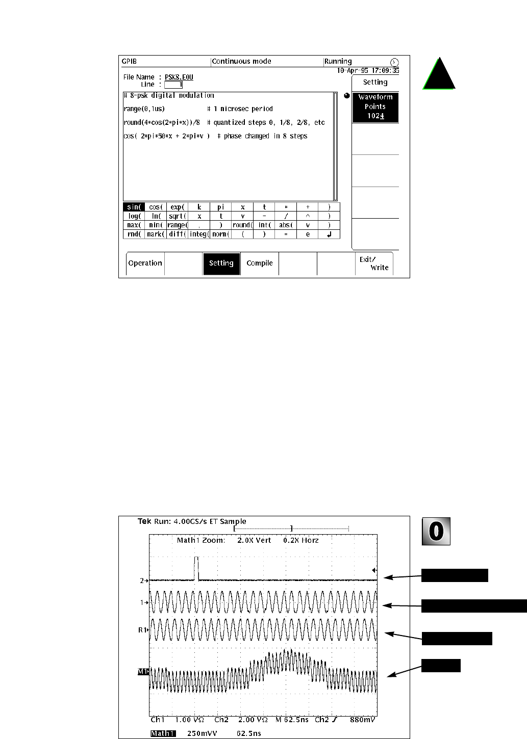
Figure 23 shows the resulting
AWG output. The top trace is
the marker output generating a
scope trigger pulse once per
record. The second trace is the
phase modulated waveform. The
third trace is the carrier wave-
form without the phase modula-
tion. That is, the phase argument
was removed from the final
equation line on the AWG in
Figure 22, leaving just the
expression cos (2*pi*50*x). This
waveform was captured sepa-
rately by the TDS 744A but is
synchronized to the same trigger
Figure 23. Scope plot of the marker output (top
trace) and the phase modulated 50 MHz carrier
(2nd trace). The 3rd trace is the carrier without
the modulation. The bottom trace is the product
of the unmodulated carrier (constant Φ=0) and
the modulated carrier.
Marker (trigger)
Carrier waveform
Product
Phase modulated waveform
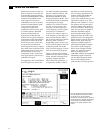
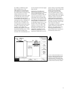
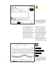
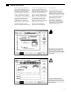
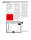
Figure 22. The equation defining the quantized
1 MHz modulating pattern and its subsequent
insertion into the phase argument of the 50 MHz
carrier. The modulating pattern shown in Figure
21 is the result of the rounding definition.