


3
One of the most challenging tasks in designing
wireless communications products is the develop-
ment of a rational approach to characterizing and
testing components, assemblies, and sub-systems.
Baseband modulation and RF signal characteristics
are becoming increasingly complex as standards
and common sense force more efficient use of the
finite electromagnetic spectrum. In addition,
manufacturers must often make equipment that is
capable of switching between different modes with
differing signal characteristics. As before, realistic
test signals are needed to simulate nominal and
worst case conditions. Yet traditional signal gener-
ators with limited modulation capabilities are
inadequate and it is not always feasible to have a
test department develop customized systems.
Test equipment has historically allowed two
approaches. If a standard has reached a threshold
of maturity, then you could obtain a
generator/analyzer that addresses that standard—
from a traditional FM broadcast to a digital PCS
system. Or you could concoct a combination of
signal, RF, and pattern generators to simulate the
desired test signal. The former approach is excel-
lent for production and field service applications
but lacks flexibility for development applications.
The latter approach often turns into an expensive
kluge providing both inconsistent performance and
limited flexibility.
More recently, test equipment manufacturers have
filled the gap between the two approaches with the
arbitrary waveform generator (AWG). The AWG is
the signal generator equivalent to the computer
spreadsheet; you can create limitless “what-if”
waveforms to more thoroughly evaluate or test new
concepts, prototype circuits, or production sub-
assemblies. Like a spreadsheet, the power of the
AWG comes from the ability to define and re-
define a signal’s value as a function of time. But a
blank spreadsheet is of little use—how do you get
the first waveform to appear at the BNC connector?
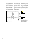
The most straightforward method is the record-
playback technique. A live signal is recorded into
the memory of a digital oscilloscope, and the
record is transferred to the AWG for playback. This
method is expedient but has limited flexibility.
Creating and editing a customized signal is a more
powerful technique and is the focus of this note:
once created, re-creating a complex signal at a later
date is as simple as retrieving it from memory—
rather than re-cabling and re-configuring an assort-
ment of interconnected generators.
Ironically, the flexibility of an AWG can make it
difficult to select a model that fits a given applica-
tion. For example, you will not find a specification
that explicitly defines an AWG’s ability to generate
a particular modulation type. In general, an AWG’s
ability to generate a specific signal must be demon-
strated by example.
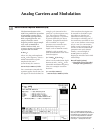
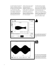
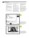
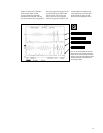
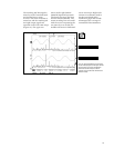
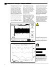
In this paper, we begin with examples of basic
AM-FM analog signals and introduce variations
such as multiple carriers and multiple modulation
signals (e.g., FM stereo). Then we demonstrate that
digital modulation generation is a straightforward
extension of basic analog modulation.
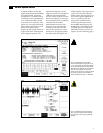
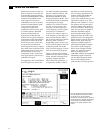
Throughout this application tutorial, we have used
the Tektronix AWG 2021 Arbitrary Waveform
Generator as the signal source, and the Tektronix
TDS 744A oscilloscope to capture and analyze
signals. The AWG 2021 provides the signal capa-
bilities, modulation features, and bandwidth
essential to effective wireless communications
testing. The TDS 744A is an ideal complement to
the AWG 2021 and is unique in its ability to
capture signal minutiae.
Certain test setups described in this book may
require external RF generators to provide carrier
signals, which are then modulated by the baseband
signal from the AWG 2021. There are many appro-
priate RF signal sources available today, including
products from Tektronix, Rohde & Schwarz, and
others. For more information about RF sources,
contact your local Tektronix representative.
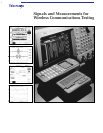
Introduction
Signals and Measurements for
Wireless Communications Testing