Creating and Using Math Waveforms
3- 206
CSA7000 Series, TDS7000 Series, & TDS6000 Series Instruments User Manual
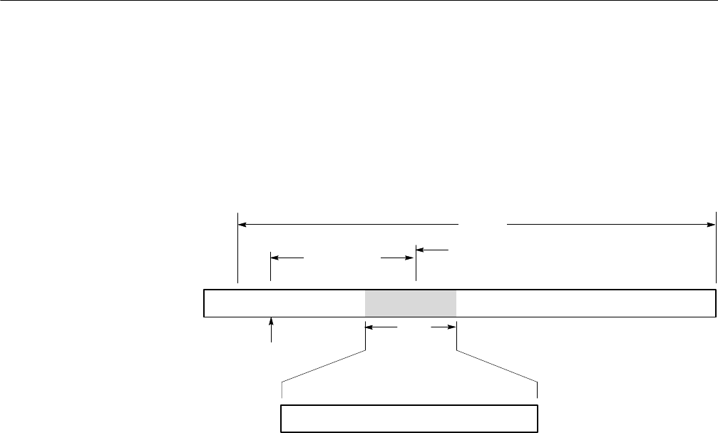
Using the gate controls. Gating determines what portion of the acquired
waveform is transformed into the frequency domain. The gate has a position and
a width control.
The gate position is the time in seconds from the trigger location to the center
50% position of the gate interval (see Figure 3--46). The position and width units
are seconds.
Gate
width
Zero phase reference
Time domain acquisition
Frequency domain samples
Gate position
Gate
Trigger
position
Duration
Figure 3- 46: Definition of gate parameters
The gate must reside within the duration interval of the source waveform. If the
source waveform duration is adjusted and the gate position and width would
result in the gate being outside of that duration then the gate position or width is
set within the limits.
The width of the gate affects the resolution bandwidth of the s pectral analyzer.
See Using Spectral Math Controls on page 3--203 for more details.
The data contained in the gated region is transformed to the frequency domain.
The gate is identified on the display using dashed markers (similar to cursors).
The default gate width setting is equal to the duration of the source waveform.
