


6
GB
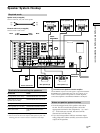
Hooking Up the Components
AC OUTLET
RL
AUDIO OUT VIDEO
OUT
OUTPUT
VIDEO
OUT
VIDEO
IN
AUDIO
OUT
AUDIO
IN
INPUT OUTPUT
L
RL
AUDIO OUT VIDEO
OUT
OUTPUT
VIDEO
IN
INPUT
VIDEO
OUT
VIDEO
IN
AUDIO
OUT
AUDIO
IN
L
INPUT OUTPUT
IMPEDANCE USE 4 - 16Ω
INOUT
ç
ç
INOUT
ç
ç
+
–
SPEAKERS
FRONTREAR CENTER B A
LRLRLR
R
L
R
L
R
IN
REC
OUT
IN
IN
OUT
IN
IN
IN
OUT
IN
CENTER
SUB WOOFERREARFRONT
CENTER
SUB
WOOFER
REARFRONT
TV/
LD
DVD
VIDEO 1
MONITOR OUT
VIDEO 2
REC
OUT
L
R AUDIO
S-VIDEO
DVD
IN COAX
CD
IN COAX
DVD
IN OPT
TV/LD
IN OPT
MD/DAT
IN OPT
MD/DAT
OUT OPT
CD
IN OPT
VIDEO
L
2ND AUDIO OUT
PRE OUT5.1CH INPUT
4 Ω 8 Ω
IMPEDANCE
SELECTOR
TAPE
MD/
DAT
CD
R
R
CONTROL
A1
SIGNAL GND
y
LR
TUNER
LR
PHONO
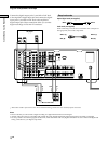
Yellow Yellow
To the front panel
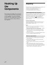
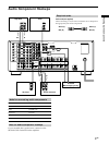
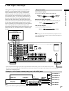
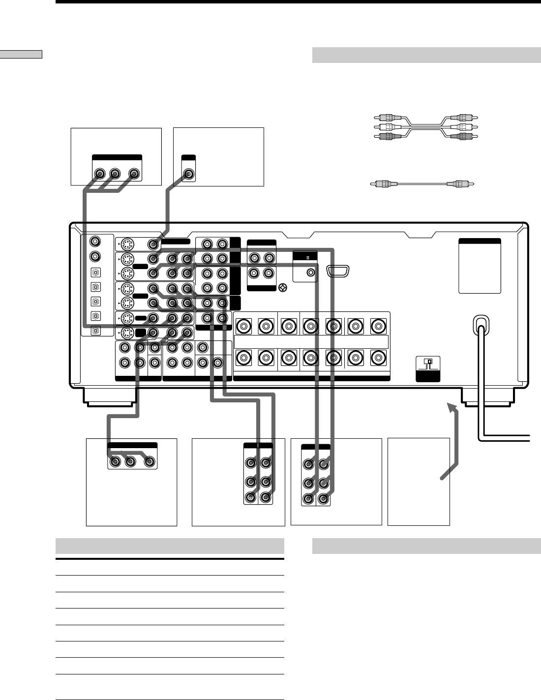
Note on video component hookups
You can connect your TV’s audio output jacks to the TV/
LD AUDIO IN jacks on the amplifier and apply sound
effects to the audio from the TV. In this case, do not
connect the TV’s video output jack to the TV/LD VIDEO
IN jacks on the amplifier. If you are connecting a separate
TV tuner, connect both the audio and video output jacks
to the amplifier as shown above.
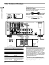
z
When using the S-video jacks instead of the video jacks
Your monitor must also be connected via an S-video jack. S-video
signals are on a separate bus from the video signals and will not
be output through the video jacks.
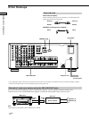
Jacks for connecting video components
Connect a To the
TV tuner TV/LD jacks
VCR VIDEO 1 jacks
Additional VCR VIDEO 2 jacks
DVD player DVD jacks
LD player TV/LD jacks
TV monitor MONITOR VIDEO OUT jack
Camcorder or video game VIDEO 3 INPUT jacks on the
front panel
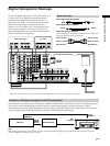
Required cords
Audio/video cords (not supplied)
When connecting a cord, be sure to match the color-coded pins to
the appropriate jacks on the components.
Video cord for connecting a TV monitor (not supplied)
Video Component Hookups
Camcorder
or video
game
TV monitor
TV tuner
DVD player
Yellow (video) Yellow (video)
White (L/audio) White (L/audio)
Red (R/audio) Red (R/audio)
VCR
VCR