


17
Connection
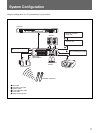
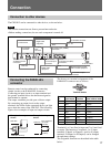
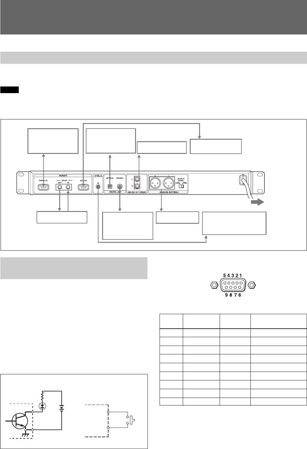
Connection to other devices
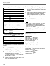
The CDP-D12 can be connected to other devices, as shown below.
Notes
• Be sure the connections are firm to prevent hum and noise.
• Before making connections, be sure each component is turned off.
Connecting the PARALLEL
connector
Remote control can be conducted by connecting
simple circuits to the PARALLEL connector.
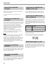
Connecting an input circuit to an input terminal and
the ground terminal allows the function assigned to
that terminal to operate.
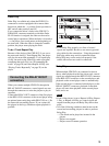
The output terminals provide open collector output.
By connecting an output circuit to the output
terminals, the LEDs on the connected device can light
up to show the status of the CDP-D12. The following
figures show examples of input and output circuits.
Example of an output
circuit
The factory-set terminal assignments of the
PARALLEL connector are as follows:
Terminal number
CDP-D12
Input terminals
(1st to 5th
terminals)
GND (6th
terminal)
Example of an input
circuit
CDP-D12
Output
terminals (7th to
9th terminals)
GND (6th terminal)
Control device
To parallel
connector
PC, etc.
Digital audio
equipment
To optical
input
connector
Mixer
To analog input (UNBAL)
connectors
To an AC outlet
Mixer
To analog input (BAL)
connectors
Digital audio
equipment
To coaxial input
connector
Supplied remote control
unit or control equipment
To control S output
connector
CDP-D12
To RELAY IN/OUT
connectors
To RS-232C connector
Terminal
No.
Input/output Function Name in Menu mode
1 Input PLAY P.Input1
2 Input PAUSE P.Input2
3 Input STOP P.Input3
4 Input AMS+ P.Input4
5 Input AMS– P.Input5
6GND — —
7 Output PLAY P.Output1
8 Output PAUSE P.Output2
9 Output NO DISC P.Output3
Terminals 1 to 5 are fixed to input and 7 to 9 are fixed
to output. The function of terminals 1 to 5 (input
terminals, P.Input1 to P.Input5 ) and 6 to 9 (output
terminals, P.Output1 to P.Output3) can be changed
through menu settings.
The assignable functions are described in the table
below: