


Function of Parts and Controls
14
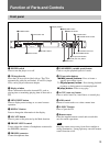
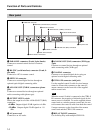
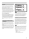
Rear panel
1 PARALLEL connector (D-sub, 9-pin, female)
Connects to external control devices for remote
control.
2 RS-232C (serial interface) connector (D-sub, 9-
pin, male)
Connects to a PC for remote control.
3 OPTICAL connector
Connects to external digital devices through an
optional optical digital connecting cable.
4 ANALOG OUT (UNBAL) connectors (phono
jack)
Connects to external devices through an optional
audio connecting cable (phono type).
5 OUTPUT LEVEL switch
Selects the output level of the ANALOG OUT (BAL)
connectors.
+4 dBu: Outputs digital–20 dB signals at +4 dBu.
–10 dBu: Outputs digital–20 dB signals at –10
dBu.
6 AC power cord
Connects to an AC outlet.
7 ANALOG OUT (BAL) connectors (XLR type,
3-pin)
Connects to external devices through an optional
audio connecting cable (XLR type).
8 COAXIAL connector
Connects to an external digital device using an
optional coaxial digital connecting cable.
9 CTRL-S IN connector (mini jack)
Use the supplied control S cable for wired remote
control to connect this connector to the control S
output connector on the front side of the supplied
remote control unit.
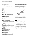
Note
When the control S cable is connected to the CTRL-S
IN connector, the reception of infrared signals by the
remote sensor is disabled. To use the supplied remote
control unit as a wireless remote control unit, be sure
to disconnect the control S cable from both the control
S output connector on the front side of the remote
control unit and the CTRL-S IN connector.
0 RELAY IN/OUT connectors
Use for Relay Play with multiple CDP-D12s.
1 PARALLEL connector
2 RS-232C (serial interface) connector
3 OPTICAL connector
4 ANALOG OUT (UNBAL) connectors
5 OUTPUT LEVEL switch
6 AC power cord
7 ANALOG OUT (BAL) connectors
8 COAXIAL connector
0 RELAY IN/OUT connectors
9 CTRL-S IN connector