


69
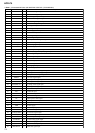
HCD-C5
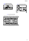
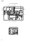
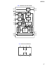
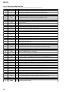
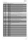
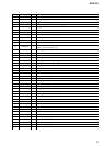
• IC151 CXD2662R
• (DIGITAL SIGNAL PROCESSOR, EFM/ACIRC ENCODER/DECODER, SHOCK PROOF MEMORY CONTROLLER,
ATRAC ENCODER/DECODER) (BD (MD) BOARD)
I/OPin NamePin No. Description
O
O
O
O
I
I (S)
I (S)
O (3)
O (3)
I (S)
O
O
I
O
O
I
O
I
I
I
O
I
I
I
I
O
O
O
O
—
O
O
O
O
—
O
O
O
O
O
MNT0 (FOK)
MNT1 (SHCK)
MNT2 (XBUSY)
MNT3 (SLOC)
SWDT
SCLK
XLAT
SRDT
SENS
XRST
SQSY
DQSY
RECP
XINT
TX
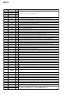
OSCI
OSCO
XTSL
DIN0
DIN1
DOUT
DATI
LRCKI
XBCKI
ADDT
DADT
LRCK
XBCK
FS256
DVDD
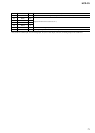
A03 to A00
A10
A04 to A08
A11
DVSS
XOE
XCAS
A09
XRAS
XWE
1
2
3
4
5
6
7
8
9
10
11
12
13
14
15
16
17
18
19
20
21
22
23
24
25
26
27
28
29
30
31 to 34
35
36 to 40
41
42
43
44
45
46
47
Focus OK signal output terminal “H” is output when focus is on (“L”: NG) Not used (open)
Track jump detection signal output to the MD mechanism controller (IC1001)
Busy monitor signal output to the MD mechanism controller (IC1001)
Spindle servo lock status monitor signal output to the MD mechanism controller (IC1001) (open)
Writing serial data signal input from the MD mechanism controller (IC1001)
Serial data transfer clock signal input from the MD mechanism controller (IC1001)
Serial data latch pulse signal input from the MD mechanism controller (IC1001)
Reading serial data signal output to the MD mechanism controller (IC1001)
Internal status (SENSE) output to the MD mechanism controller (IC1001)
Reset signal input from the MD mechanism controller (IC1001) “L”: reset
Subcode Q sync (SCOR) output to the MD mechanism controller (IC1001)
“L” is output every 13.3 msec Almost all, “H” is output
Digital In U-bit CD format subcode Q sync (SCOR) output to the MD mechanism controller
(IC1001) “L” is output every 13.3 msec Almost all, “H” is output
Laser power selection signal input from the MD mechanism controller (IC1001)
“L”: playback mode, “H”: recording mode
Interrupt status output to the MD mechanism controller (IC1001)
Magnetic head on/off signal output to the over write head drive (IC181)
System clock signal (90.3168 MHz) input terminal
System clock signal (512Fs=90.3168 MHz) output terminal Not used (open)
Input terminal for the system clock frequency setting
“L”: 45.1584 MHz, “H”: 90.3168 MHz (fixed at “H” in this set)
Digital audio signal input terminal when recording mode Not used
Digital audio signal input terminal when recording mode
Digital audio signal output terminal when playback mode
Recording data input from the A/D converter (IC1005)
L/R sampling clock signal (44.1 kHz) input from the D/A converter (IC1006), A/D converter
(IC1005)
Bit clock signal (2.8224 MHz) input from the D/A converter (IC1006), A/D converter (IC1005)
Recording data input terminal Not used (fixed at “L”)
Playback data output terminal Not used (open)
L/R sampling clock signal (44.1 kHz) output terminal Not used (open)
Bit clock signal (2.8224 MHz) output terminal Not used (open)
Clock signal (11.2896 MHz) output terminal Not used (open)
Power supply terminal (+3.3V) (digital system)
Address signal output to the D-RAM (IC152)
Address signal output to the D-RAM (IC152) (open)
Address signal output to the D-RAM (IC152)
Address signal output to the external D-RAM Not used (open)
Ground terminal (digital system)
Output enable signal output to the D-RAM (IC152) “L” active
Column address strobe signal output to the D-RAM (IC152) “L” active
Address signal output to the D-RAM (IC152)
Row address strobe signal output to the D-RAM (IC152) “L” active
Write enable signal output to the D-RAM (IC152) “L” active
* I (S) stands for schmitt input, I (A) for analog input, O (3) for 3-state output, and O (A) for analog output in the column I/O.