


18
HCD-C5
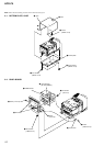
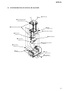
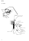
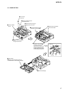
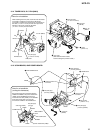
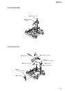
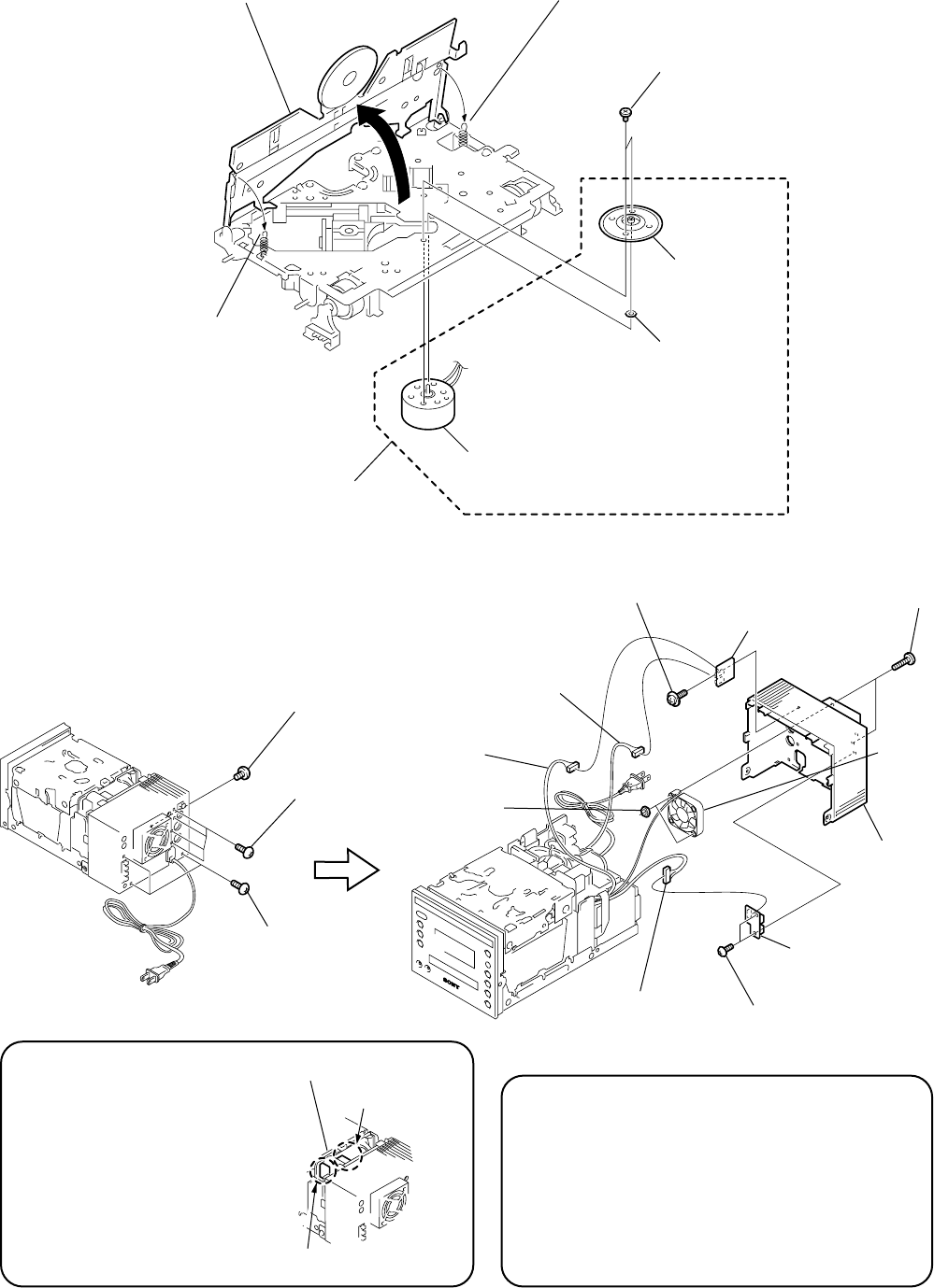
3-13. JACK BOARD, HP BOARD, REAR COVER
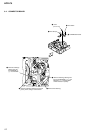
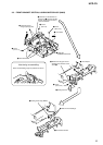
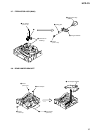
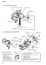
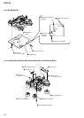
3-12. SPINDLE MOTOR ASSY (M904)
4
two screws
(+P 1.7 x 2.2)
5
turn table
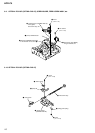
1
clip arm spring (L)
2
clip arm spring
3
open to direction of the arrow
A
A
6
washer
7
spindle motor
8
spindle motor assy
(M904)
3
three screws
(+BV 3 x 8)
2
four screws
(+BV 3 x 12)
1
screw
(+BVTT 3 x 5)
8
two screw
s
(+B 4 x 16)
q;
rear cover
3
JACK board
1
two screws
(+BV 3 x 8)
9
two nuts
(N4)
5
connector
(CN109)
6
connector
(CN110)
2
connector
(CN107)
4
screw
(+PTPWH 3 x 8)
7
HP board
D.C.fa
n
(M901)
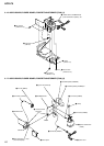
Note for re-installation-1
When installing the rear cover,
be careful that the three harnesses
coming from
“
2
Connector (CN107)”,
“
5
Connector (CN109)”,
“
6
Connector (CN110)”,
and the harness coming from the
DC fan (M901) must not contact the
heat sink (IC902) and the diode
(D981) and the heat sink (IC904).
heat sink (IC902)
POWER board
diode (D981)
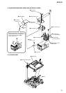
Note for re-installation-2
When installing the rear cover, be careful that the three
harnesses coming from
“
2
Connector (CN107)”,
“
5
Connector (CN109)”,
“
6
Connector (CN110)”,
and the harness coming from the D.C. fan (M901) must not
be pinched by the rear cover, the UCOM board, power
transformer (T900) and tuner pack.