


19
HCD-C5
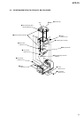
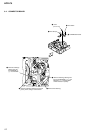
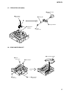
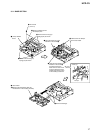
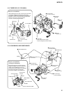
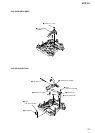
3-14. TUNER PACK, D. C. FAN (M901)
1
screw
(+BV 3 x 8)
3
tuner pack
(After slanted toward outside,
remove it straight up toward outside.)
2
wire (flat type)
(11 core or 15 core)
wire (flat type)
(11 core or 15 core)
tuner pack
4
connector
(CN105)
AUDIO board
CN106
5
D.C. fa
n
(M901)
D.C.fan (M901)
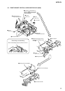
Note for re-installation
When installing the tuner pack, insert the three harnesses
connected to CN105 and connected to CN106 and
connected to CN108 of the AUDIO board, in between the
flat cable (11 core or 15 core) and the tuner pack in the
direction of the arrow so that the flat cable
(11 core or 15 core) must be inserted.
CN108
CN105
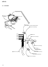
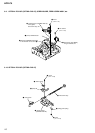
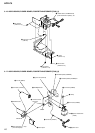
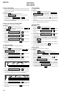
3-15. UCOM BOARD, AMP POWER BOARD
4
two screws
(+BVTT 3 x 5)
9
UCOM board
CN205
CN206
CN901
CN852
8
AMP POWER baord
1
wire (flat type)
(19 core) (CN101)
2
wire (flat type)
(19 core) (CN203)
7
board to board
connector
6
wire (flat type)
(16 core) (CN201)
5
board to board
connector
3
connector
(CN851)
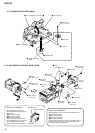
A
A
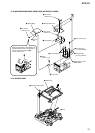
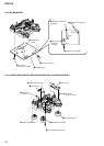
Note for re-installation
(routing the harnesses)
Be careful that the two harnesses between
CN995 and CN992 of the power transformer
(T900) and the POWER board must not
contact the heat sink (IC902) on the POWER
board and the flat cable (19 core) that
is inserted to CN203 on the UCOM board.
wire (flat type)
(19 core)
CN203
CN851
CN995
CN992 power transformer (T900)
POWER baord
AMP POWER
board
UCOM board
heat sink (IC902)