


9
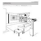
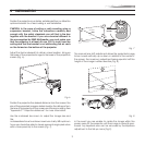
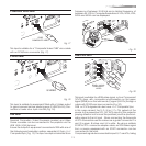
Position the projector on a stable, suitable platform or utilise the
optional bracket for a fixed ceiling or wall installation.
CAUTION: In the case of ceiling or wall mounting using a
suspension bracket, follow the instructions carefully and
comply with the safety standards you will find in the box
together with the bracket. If you use a bracket different to
the one supplied by SIM2 Multimedia, you must make sure
that the projector is at least 65 mm (2-9/16 inch) from the
ceiling and that the bracket is not obstructing the air vents
on the lid and on the bottom of the projector.
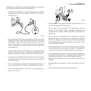
Adjust the feet underneath to obtain a level position, lining up
the base of the projected image to the base of the projection
screen (Fig. 6).
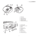
DIGITAL
INPUT
AUDIO
OUT
ZOOM
CONTROL (RS 232)
GRAPHICS RGB
R/Cr
G/Y
B/Cb
HV
1
2
4
3
5
ATTENTION: pour ne pas compromettre
la protection contre les resque d'incende
remplacer par un fusible de meme type
et de mems caracteristique
CAUTION: for continued protection against
risk of fire, replace
only with same type
and rating fuse.
Fig. 6
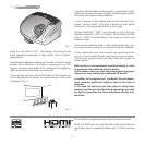
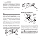
Position the projector the desired distance from the screen: the
size of the projected image is determined by the distance from
the lens of the projector to the screen and the zoom setting. See
“Appendix C”: Projection distances” for more information.
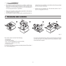
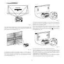
Use the motorised lens zoom to adjust the image size and
the
motorised lens focus to achieve maximum clarity. With optimum
focus you should be able to clearly see each single pixel when
within close proximity to the screen (Fig. 7).
F1
ZOOM
FOCUS
F2
ZOOM
ZOOM
ZOOM
ZOOM
FOCUS
FOCUS
FOCUS
ZOOM
FOCUS
DIGITAL
INPUT
AUDIO
OUT
ZOOM
CONTROL
(RS 2
32)
GRAPH
ICS RGB
R/Cr
G/Y
B/Cb
HV
1
2
4
3
5
ATTENTION: pour ne pas
compromettre la protection contre les
resque d'incende remplacer par un
fusible de meme type et de mems
caracteristique
CAUTION: for continued protection
against risk of fire, replace
only with same type
and rating fuse.
Fig. 7
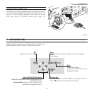
The manual lens shift adjustment allows the projected image
to be moved vertically, up or down, in relation to the centre of
the screen; the maximum adjustment being equal to half the
height of the image in either direction (Fig. 8).
DIGITAL
INPUT
AUDIO
OUT
ZOOM
CONTROL (RS 232)
GRAPHICS RGB
R/Cr
G/Y
B/Cb
HV
1
2
4
3
5
ATTENTION: pour ne pas compromettre
la protection contre les resque d'incende
remplacer par un fusible de meme type
et de mems caracteristique
CAUTION: for continued protection against
risk of fire, replace
only with same type
and rating fuse.
Fig. 8
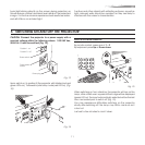
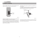
In the event you are unable to centre the image within the
screen area, tilt the projector until the image is correctly posi-
tioned. Any keystone error can be removed by the Keystone
adjustment in the Set up menu (Fig.9).
4 INSTALLATION