


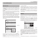
13
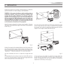
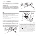
Frequency of between 32-80 kHz and a Vertical frequency of
between 48-100 Hz. Computer Resolutions of VGA, SVGA, XGA,
SXGA and UXGA can be displayed.
HDMI
AUDIO
OUT
ZOOM
CONTROL (RS 232)
GRAPHICS RGB
R/Cr
G/Y
B/Cb
HV
1
2
4
3
5
et de mems caracteristique
CAUTION: for continued protection against
risk of fire, replace
only with same type
and rating fuse.
Fig. 19
RGB/YCrCb INPUT
DIGITAL
INPUT
AUDIO
OUT
CONTROL (RS 232)
GRAPHICS RGB
R/Cr
G/Y
B/Cb
HV
3
5
ATTENTION: pour ne pas compromettre
la protection contre les resque d'incende
remplacer par un fusible de meme type
et de mems caracteristique
CAUTION: for continued protection against
risk of fire, replace
only with same type
and rating fuse.
RGSB - YSCRCB
COMPONENT
VIDEO
Fig. 20
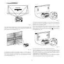
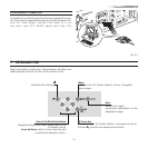
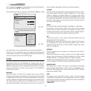
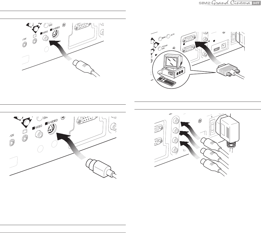
This input is suitable for a RGB video signal, or for a Component
(YCrCb) type, with composite synchronisation on the green
signal (RGsB) or on the luminance (Y) signal (YsCrCb) through a
cable with RCA/Phono type connector (Fig. 20).
RGB or YCrCb signals can also have H+V Composite Sync.
In this case connect the R, G, B (or Y, Cr, Cb) outputs of the
source to the respective R/Cr, G/Y, B/Cb inputs of the projector
(paying attention not to invert the positions) and the synchroni-
sation signal to the HV input . When connecting the three sets
of RCA connectors use the colours as a guide: connector R is
red, G is green, B is blue and HV is white. By using a suitable
SCART to RCA connector adapter cable, an RGB video signal
from a source equipped with an SCART connector can be
connected to this input.
Component signals are connected to inputs Y, Cr and Cb, taking
COMPOSITE VIDEO INPUT
CONTROL (RS 232)
B/Cb
HV
1
2
CVBS
COMPOSITE VIDEO
Fig. 17
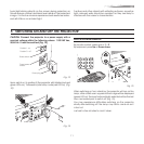
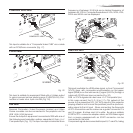
This input is suitable for a “Composite Video CVBS” via a cable
with an RCA/Phono connector (Fig. 17).
S-VIDEO INPUT
S-VIDEO
CONTROL (RS 232)
B/Cb
HV
1
2
Fig. 18
This input is suitable for equipment fitted with a S-Video output
to give improved picture performance (S-VIDEO/S-VHS) Con-
nection is made via a 4-pin mini-DIN (Fig. 18).
VGA INPUT
Personal Computers, Video Processors (scalers) and Video
Game consoles can be connected to the projector via the
HDB 15-Pin (VGA) terminal.
Ensure the output of equipment connected is RGB with one of
the following synchronisation options: separate H/V Sync, H+V
Composite Sync (Fig. 19). This input accepts a Horizontal Scan