


20
IMAGE
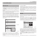
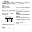
This menu features adjustments relating to picture position,
aspect ratio, etc.
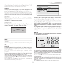
ASPECT
This adjustment allows you to change the dimensions and
aspect ratio (relationship between width and height) of the
displayed image. There are five preset aspects available and
three personalised aspects (with user-settable parameters). You
can select a different aspect for each source: the selected
aspect ratio will be automatically called the next time the
relative source is called.
You can also select the required aspect ratio by repeatedly
pressing the key, or by pressing and a numerical key
(1...8). The following aspects are available.
NORMAL
: projects the image occupying the full height of the
screen while maintaining the aspect ratio of the input signal.
When the input signal aspect ratio is 4:3 black vertical bands
are displayed on the right and left of the picture.
ANAMORPHIC
: allows a 16:9 picture to be displayed correctly.
LETTERBOX
: serves to display 4:3 letterbox image (with source si-
gnal having black bands above and below the picture) so that
it fills the 16:9 screen and maintains the correct aspect ratio.
PANORAMIC
: this aspect stretches the 4:3 image, slightly cropping
the upper and lower parts.
Panoramic is ideal for displaying a 4:3 image on the 16:9
screen of the Display.
PIXEL TO PIXEL
: this aspect displays the image as it is input without
adapting it to the screen.
The image is projected in the centre of the screen and if its ho-
rizontal and/or vertical dimensions are smaller than the display,
it is bounded by vertical and/or horizontal black bands.
USER 1, 2, 3:
When none of the preset formulas are suitable, the
User formulas are available, with the facility for continuous
horizontal and vertical adjustment of picture size.
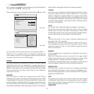
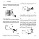
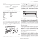
SCREEN CONTROL
For each aspect chosen, the SCREEN CONTROL command
allows you to reframe the screen to a variety of aspect ratios
and screen size, using an appropriate screen-masking interface
connected to the 12 V output socket (please refer to the screen
manufacture’s manual)
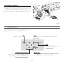
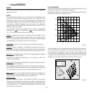
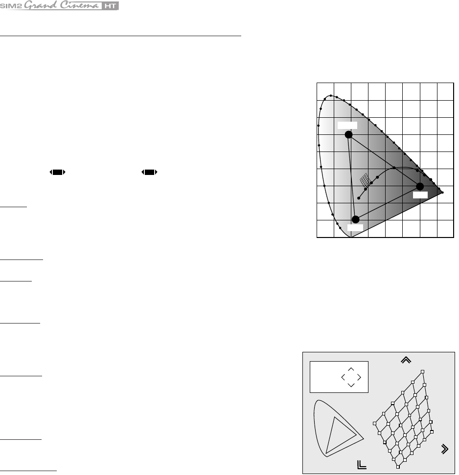
COLOR TEMPERATURE
The color temperature adjustment is made by positioning the
white point inside CIE cromaticity diagram.
The systems allows to choose from 36 predefined white points
inside the neutral color area (Fig.29).
)NFINITY
K
8
9
'REEN
2ED
"LUE
Fig. 29
The correlated color temperature varies along horizontal lines,
low temperatures are present in the right side (where the red
component is increased), in the left side of the diagram you
can find high temperature values ( in which blue component
is higher). The points along the lower horiziontal line (Fig.30)
represent colors that belong to the black body curve.
Fig. 30