


14
care to observe the correspondence with the outputs on the
source. The video signals that can be connected to this input
can have horizontal scanning frequencies of 15 kHz (standard
video resolution), 32 kHz, or higher (progressive scanning video,
high definition video).
Some sources provide the facility to choose between a pro-
gressive signal or an interlaced signal. Although in general a
progressive signal is higher quality than an interlaced signal, it
is often preferable to perform the deinterlacing operation on
the projector rather than on the source.
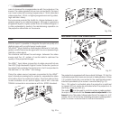
HDMI™
With this input it is possible to integrate the optimal quality of a
digital image with a multichannel audio signal.
The HDMI™ (High Definition Multimedia Interface) in fact inte-
grates a multichannel audio signal with the uncompressed high
definition video signal.
The interface also allows the exchange between the video
source and the HT system of control data to optimise the
quality of the projected image.
The HDMI™ input allows connection to video sources that use
the HDCP (High-Bandwidth Digital Content Protection) protocol
to protect their contents. This protocol is in fact incorporated in
the definition of the HDMI™ technology.
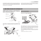
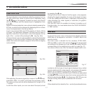
Once the video source has been connected to the HDMI™
input, internal processing by the projector separates the video
information from the audio information. This information is then
made available via an optical digital output with a female
TOSLINK connector in accordance with the S/PDIF standard.
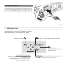
HDMI
AUDIO
OUT
ZOOM
CONTROL (RS 232)
GRAPHICS RGB
R/Cr
G/Y
B/Cb
HV
1
2
4
3
5
CAUTION: for continued protection against
risk of fire, replace
only with same type
and rating fuse.
Fig. 21a
HDMI
AUDIO
OUT
ZOOM
CONTROL (RS 232)
GRAPHICS RGB
R/Cr
G/Y
B/Cb
HV
1
2
4
3
5
CAUTION: for continued protection against
risk of fire, replace
only with same type
and rating fuse.
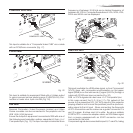
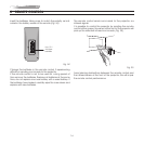
MOTORISED PROJECTION SCREEN OUTPUT
ZOOM
CONTROL (RS 232)
GRAPHICS RGB
1
2
4
Fig. 22
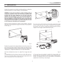
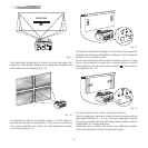
The projector is equipped with two outputs (Voltage: 12 Vdc) for
motorised projection screen and screen masking systems. These
12V outputs should be connected to the appropriate screen
interface provided by the screen manufacturer (Fig. 22).
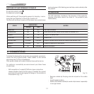
The +12V output is activated when the projector is switched
on (green LED on) and is de-activated when the projector is in
stand-by mode (red LED on).
The output can be used to control a screen masking system;
its output can be set with the Screen control adjustment in the
Aspect menu. This output allows reduction in the area of a 16:9
screen, into a 4:3 format, by activating a screen masking system
(refer to screen manufacturer for further information).
Fig. 21b