


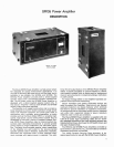

SR105
Power Amplifier
OPERATING INSTRUCTIONS
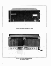
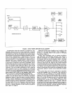
FUNCTIONAL IDENTIFICATION (Refer to Figures 1 and 2,
Page 2).
1. OUTPUT VOLTAGE Meter
-
lndicates Amplifier out-
put voltage in percentage of maximum voltage.
2. VOLUME
Control
-
Controls Amplifier output level.
3. THERMAL OVERLOAD Indicator Lamp
-
lndicates
Amplifier shutdown due to excessive heat sink temper-
ature.
4. POWER ON-OFF Switch
-
Applies ac power to Ampli-
fier.
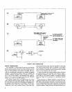
5. BALANCED BRIDGING
lnput Jack
-
Provides for bal-
anced bridging, high-impedance input connection.
6.
3AGl5A Ac Line Fuse
-
Protects Amplifier ac input
line aaainst overload.
-
7. Ac Line Cord
-
Connects ac power to Amplifier power
supply.
8. DIRECT OUTPUT Jacks (Four)
-
Provide for output
connection to
direct-coupled speaker systems.
9. DIRECT OUTPUT
Terminal Strip
-
Provides for output
connection to
direct-coupled speaker systems.
10. 70V-OFF Switch
(SRIO5A Amplifier only)
-
Activates
70-volt output transformer for use with distributed
speaker systems.
11. 70V OUTPUT Terminal Strip
(SRI05A Amplifier only)
-
Provides for output connection to 70-volt distributed
speaker systems.
12. SPARE FUSE
Fuseholder- Holds spare 3AG-5A
power
supply fuse.
13. UNBALANCED PARALLELED
HlGH IMPEDANCE In-
put Jacks (Two)
-
Provide unbalanced (one side
grounded) input connections for use with
high-im-
pedance sources.
14.
70-Volt Output Cover Plate (SRIOSB Amplifier only)
-
Covers pre-drilled and marked area where Switch (10)
and Terminal Strip (11) are located.
GENERAL OPERATING INSTRUCTIONS
WARNING
Voltages in this equipment are hazardous to life. Make
all input and output connections with ac power dis-
connected. Refer servicing to
qualified service per-
sonnel.
DIRECT SPEAKER OUTPUT OPERATION
(MODEL
SRIO5A and SR105B AMPLIFIERS)
1. Install Amplifier before making electrical connections.
Using hardware supplied, secure
Amplifier in rack or
carrying case, allowing at least 51 mm
(2
in.) above
and behind case for ventilation. Use forced-air cooling
for multiple-amplifier installations.
2. Set Switches
(4,lO) to OFF and VOLUME Control (2)
to
0.
3. Connect required speakers to Amplifier DIRECT OUT-
PUT jacks (8)
andlor to terminal strip (9), using proper
wire size and arranging speaker connections for
total
speaker load impedance as close to 4 ohms as possible.
Remove DIRECT OUTPUT Cover (14) and use right-
angle phone plugs to connect speakers to Amplifier.
When using DIRECT OUTPUT Terminal Strip (9), thread
wires through Cover grommet. Replace cover.
CAUTION
In multiple speaker installations, be sure not to ex-
ceed maximum power rating of any speaker.
4. Connect audio
console or microphone mixer output to
Amplifier
UNBALANCED PARALLELED HlGH IMPE-
DANCE
lnput Jack (13) (standard phone jack). For in-
terconnections up to 15m (50 ft), use
single-conduc-
tor, shielded, low-capacitance cable. For intercon-
nections longer than 50 ft, use 600-ohm balanced line
into Amplifier BALANCED BRIDGING lnput Jack (5)
(professional, 3-pin, female audio connector).
5.
Connect additional power amplifiers or other auxiliary
equipment as required to remaining Amplifier input
jacks.
6. Connect
line cord (7) to grounded 120 Vac &lo%,
50/60
Hz source capable of supplying 450 watts.
7.
With VOLUME Control (2) set at 0, turn front-panel
POWER Switch (4) on. Adjust VOLUME Control to de-
sired
amplifier operating level.
CONSTANT-VOLTAGE 70-VOLT SPEAKER OUTPUT
(MODEL
SR105A AMPLIFIER ONLY)
1. Connect
auxiliary equipment as for direct speaker op-
eration in steps 1, 2, 4, 5 and 6 above.
2. Connect required speakers to 70V OUTPUT Terminals
(11) and, if necessary, DIRECT OUTPUT Connectors
(8,9). Total speaker impedance should be as close to 33
ohms as possible. Be
careful not to exceed Amplifier
150-watt power output capability. (See Output Con-
nections, Page 6.)
3. Connect audio
console or microphone mixer output to
Amplifier UNBALANCED PARALLELED HlGH IMPE-
DANCE Input Jack (13) (standard phone jack). For in-
terconnections up to 15m (50 ft), use
single-conduc-
tor, shielded, low-capacitance cable. For intercon-
nections longer than 50 ft, use 600-ohm balanced line
into Amplifier BALANCED BRIDGING lnput Jack (5)
(professional, 3-pin, female audio connector).
4. Turn 70V-OFF Switch (10) to 70V.
5.
Connect line cord (7) to grounded 120 Vac *lo%,
50160
Hz
source.
6.
With VOLUME Control
(2)
set at
0,
turn front-panel
POWER Switch (4) on. Adjust VOLUME Control to de-
sired amplifier operating level.