


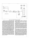
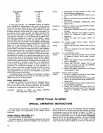
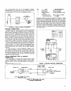

FIGURE
4.
SR105
POWER AMPLIFIER BLOCK DIAGRAM
METER
RECTIFIER
In applications where the Amplifier is located at a con-
siderable distance from the mixer-preamplifier, electrical
interference or excessive hum pickup may be encountered.
Hum pickup may also be encountered over shorter distan-
ces as a result of ground loop conditions between the units.
Under these circumstances, a balanced line, such as is
used for low-impedance microphones, should be used for
interconnections. A low-capacitance, two-conductor,
shielded cable (such as
Belden #8412 or 8422) is recom-
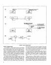
mended. A professional, three-pin, female audio connector
is required for
wnnection to the mixer-preamplifier, and a
similar three-pin male connector is necessary for connec-
tion to the Amplifier (see Figure 5B, Page 6). When wiring
these connectors, connect the cable shield to pin 1 in each
connector, one of the cable conductors to pin 2, and the
other conductor to pin 3 in each connector. For balanced
line operation, use the cable as described above to connect
the mixer-preamplifier PROGRAM OUTPUTS three-pin con-
nector labeled
LlNE LEVEL to the Amplifier LlNE LEVEL
INPUTS connector labeled BALANCED BRIDGING (5).
Since the two input jacks of the Amplifier are wired in
parallel, one jack may be used as an auxiliary, high-level,
unbalanced output to feed the signal to another Amplifier
(SR105 or similar equipment) or the high-impedance input
of a tape recorder. The three-pin input connector (5) is con-
nected through an isolation transformer in parallel with the
two input jacks (13). If not otherwise in use, the three-pin
connector may be used as a balanced, high-level, signal
source for a second Amplifier or other auxiliary equipment
(see Figure
5C, Page 6).
VOLT-
METER
(70)
Additional SR105 Power Amplifiers may be added to the
system for a fail-safe type operation where complete re-
dundancy is required. Refer to the section on Bridging
Connections (Page 11).
Certain input equipment, such as passive equalizers,
step attenuators and matching networks, may require a
600-ohm termination for optimum performance. (This is
not required with any Shure products.) When a 600-ohm
terminated input is required, a 620-ohm,
5%, %-watt re-
sistor must be connected to the terminals of the input cable
connector (see Figure 5D, Page 6). This resistor must be
connected between pins 2 and 3 of the three-pin connector,
or between the tip and sleeve terminals of the phone plug.
The resistor will fit inside the sleeve of the three-pin con-
nector or phone plug. Be careful not to damage the wires,
connections, sleeve or resistor when making this installa-
tion.
An occasion may arise where it is desirable or expedient
to feed the Amplifier from a 70-volt line. This could be in
connection with the expansion of an existing installation,
or as a result of efforts to minimize cable runs in a new in-
stallation. An input signal for the Amplifier may be derived
from a 70-volt line through the use of an attenuator (see
Adding Amplifiers in
a
70-Volt System, Page 10). When
operating from a 70-volt line, the VOLUME Control (2) on
the Amplifier should be set to the "7" position. With the
recommended attenuator, this setting will produce approxi-
mately 28.3 volts at the DIRECT OUTPUT terminals
(8,9),
or
70 volts at the 70V OUTPUT terminals
(SRlO5A Amplifier)
(1 1) when the 70-volt input line is at 70 volts.
INPUTS
0''
-
I'
UNBALANCED
a
BALANCED
BRIDGING
INPUT
DIRECT
SPEAKER
OUTPUTS
I
I
-
METER
ADJUST
FILTER
d
=
'0
11
/
?
XFMR
VOLUME
ASSEMBLY
!&
LOW-CUT 70
V
/
I
I
I
I
I
f
!&
SRIOSA AMPLIFIER ONLY. I
I
I
BALANCE
I
I
I
1
1
I
I
I
I
I
XFMR*
*
I
I
I
L
-
-
-
-
- -
-
- -
-
- -
-
-
-
- -
-
-
-1