


R39 R40 Dl2 R36
T2
C14
C15
R3
1
Q8
R35
Q7
R43 PL2 MI PL3
(XPL2) (XPL3)
Y
SRIOSA MODEL ONLY
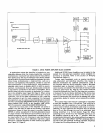
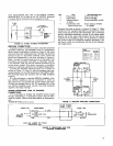
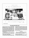
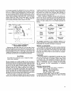
FIGURE 13. SR105 POWER AMPLIFIER TOP VIEW,
COVER REMOVED
(SRlOSA MODEL SHOWN)
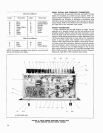
adjustment screw below the meter face until the needle is
Circuit Board. (The
SR105B Amplifier contains only a Main
properly positioned. With no load on the Amplifier (speaker
Circuit Board.) The foil side of the boards may be made
disconnected), connect an ac voltmeter across one of the
accessible for servicing without disconnecting any leads
DIRECT OUTPUT Terminals. Turn the Amplifier on and ap-
by removing the four Phillips head screws securing the
ply a 1 kHz sine-wave signal at approximately
3
volts rms
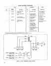
board. The boards may be completely removed as follows
to one of the Amplifier inputs. Adjust the VOLUME Control
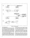
(see Figure 14, Page 14). Remove the bottom cover. On the
for 28.3 volts at the output. Remove the bottom cover and
Main Circuit Board, remove all
15
interconnecting leads
adjust the Meter Adjust resistor (R27-METER ADJ. located
from the push-on board terminals, noting connections as
on the Main Circuit Board under the chassis as shown in
listed in the table below.
Figure 14, Page 14) for a 100% reading on the OUTPUT
VOLTAGE Meter. No further adjustment is necessary.
Re-
CAUTION
place the bottom cover.
Similar wire colors are used in different circuits; make
To calibrate the meter for a 100% indication with
70.7V
sure proper re-connections can be made. Take care
output, connect the voltmeter and an appropriate load
not to bend or break the push-on terminals.
across the 70V OUTPUT terminals and proceed as above.
Remove the four Phillips head screws from the board and
PRINTED CIRCUIT BOARD REMOVAL
remove the board from the chassis.
The underside of the
SR105A Amplifier chassis contains
The Filter Circuit Board may be removed in the same
two printed circuit boards: a Main Circuit Board and a Filter
manner. Replace bottom cover after servicing boards.
13