


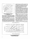
SR105
Power Amplifier
SERVICE INSTRUCTIONS
AMPLIFIER SERVICE
(See Guarantee)
The
SR105 Power Amplifier uses components of the high-
est quality, operating well within their respective ratings to
assure long life.
WARNING
Voltages in this equipment are hazardous to life.
Make all input and output connections with ac power
disconnected. Refer servicing to qualified service
personnel.
REPLACEMENT PARTS
Parts that are readily available through local electronic
parts distributors are not shown on the accompanying
Parts List. Their values are shown on the Circuit Diagram
(Figure 21, Page 25). Commercial parts not readily avail-
able and uniaue
arts
are shown on the Parts List and may
be ordered diredtly from the factory.
The commercial alternates shown on the Parts List are
not necessarily equivalents, but are electronically and
mechanically similar, and may be used in the event that
direct factory replacements are not immediately available.
To maintain the highest possible performance and reliabil-
ity, Shure factory replacement parts should be used. When
ordering replacement parts, specify the Shure Replacement
Kit Number, description, product model number and serial
number.
FUSE REPLACEMENT
To replace line fuse F2 (with no apparent problems in the
unit), disconnect the line cord and remove the rear-panel
fuseholder cap. Replace the defective fuse only with a
3AG-5A fuse.
NOTE: The following symbol
on the rear panel denotes
a
fast
operating fuse.
CAUTION
If trouble symptoms
-
overheating (thermal cycling),
erratic operation, etc. -were apparent before the
fuse blew, or if the replacement fuse blows, trouble-
shoot the Amplifier carefully to find the source of the
trouble. Do not continue to replace fuses unless the
trouble has been corrected.
The Amplifier also contains two wired-in fuses, one in
series with rear-panel line fuse F2
(FI, 3AG-8A) and one
in the meter lamp circuit (F3, SAG-1A). If replacement be-
comes necessary, replace only with identical fuses.
BOTTOM PLATE REMOVAL
To remove the chassis bottom plate, turn the Amplifier
upside-down and remove the
10 screws located at the
edges of the chassis.
COVER REMOVAL
To service components on the top of the chassis, the
protective cover grille (MP7) must be removed. This is
done by removing one screw from the top, two screws from
each side, and eight screws from the back surface. To re-
move, slide cover up and to the rear of the Amplifier.
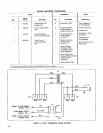
LAMP REPLACEMENT
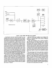
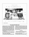
Two bayonet-base pilot lamps (PL2, PL3) illuminate the
scale of the OUTPUT VOLTAGE meter. These lamps are
mounted on the top surface of the chassis behind the meter
as shown in Figure 13, Page 13. To replace a lamp, remove
the grille cover and the nut on the lamp bracket mounting
stud. Swing the bracket up and out until the lamp is ac-
cessible. Push the lamp inward, twist it
1/8-turn counter-
clockwise, and withdraw it from its socket. After replacing
the lamp, reposition the assembly under the meter and
tighten the bracket nut. Replace the grille cover.
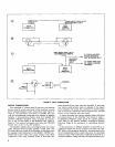
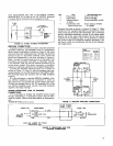
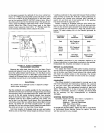
DC OUTPUT BALANCE ADJUSTMENT
In order to minimize the idle power consumption of the
Amplifier and eliminate dc offset at the direct-coupled
output, a dc balance control
(R4-DC BAL.) has been pro-
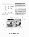
vided. This control is located on the Main Circuit Board
under the chassis, as shown in Figure 14, Page 14, and may
be reached by removing the bottom cover. The dc balance
of the Amplifier should be checked and adjusted as neces-
sary whenever any circuit components are replaced.
The dc balance adjustment is made with the Amplifier
VOLUME control
(R41) full counterclockwise and no
speaker load. If the Amplifier being adjusted is equipped
with a 70-volt output
(SR105A), the 70V-OFF Switch (S4)
should be turned off. Connect a dc voltmeter (preferably
with a 0.1 Vdc full-scale range) across the terminals of the
DIRECT OUTPUT terminal strip
(TSI).
CAUTION
The polarity of any dc voltage at the output may be
either positive or negative and could be as much as
10 volts; care should be exercised in connecting the
meter such that an on-scale reading is obtained.
Carefully adjust the dc balance control for
0 Vdc +-25 mV
at the output.
If the 70V-OFF Switch was moved to make this adjust-
ment, return it to its original position. Replace the bottom
cover.
OUTPUT VOLTAGE METER CALIBRATION
In the event that the OUTPUT VOLTAGE Meter (MI) or
its associated circuitry is repaired, a meter calibration
check and adjustment should be performed. With the
Amplifier off, check the zero position of the meter. If it is
not on zero, use a small screwdriver to turn the meter zero