


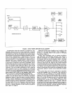
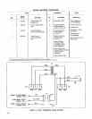

duce approximately 28.3 volts at the DIRECT OUTPUT
terminals
(8,9), or 70 volts at the 70V OUTPUT terminals
(11) when the 70-volt input line is supplying 70 volts.
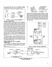
FIGURE 10. 70-VOLT SYSTEM ATTENUATOR
BRIDGING CONNECTIONS
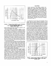
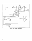
If greater power or optimum system reliability becomes
extremely important, two Amplifiers may be connected in
series (never in parallel!) to obtain an output of 400 watts
into an 8-ohm load, or 200 watts into a 16-ohm load (6 ohms
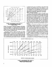
minimum load). To determine available power, divide the
actual load impedance by two and, referring to Figure 6,
Page 7, double the output power shown on the graph. This
connection also provides a fail-safe, or redundant, system:
if one Amplifier fails, the second remains functional at its
normal power output. This series connection of amplifier
outputs is commonly referred to as a bridged configuration.
Connect the Amplifier balanced inputs out of phase as
shown in Figure 11, Page 11, with the speaker load con-
nected between the two 28V terminals of the DIRECT OUT-
PUT Terminal Strips (9). Connect the two
GND
terminals
together.
If a 140-volt output is required
(SRlO5A Amplifier only),
two
SR105A Amplifiers may be connected in series as
described above, except that the 70-volt outputs are used.
Connect the speaker load to the 70V terminals (11) of the
two
SR105A Amplifiers and connect the COM terminals
together. Use Class 1 wiring.*
ADDING HEADPHONE JACK TO SPEAKER
CONNECTIONS
If it is desirable to monitor the Amplifier direct output
through headphones, a headphone output may be fabri-
cated as follows. Obtain parts listed below or their equiva-
lent.
'As
def~ned
by
U.S.
Nat~onal Electrical Code
70-VOLT
LINE
*
3-PIN MALE
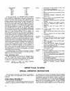
Qty. Part Recommended Type
1
Phone Jack Switchcraft 12-8
1 Phone Plug Switchcraft 280
1 Volume Control
Switchcraft
666Pl or 656
(L-Pad)
1 Transformer, 25V Essex-Stancor A-8095
Line to Voice Coil or A-8096
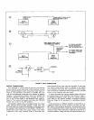
Connect the parts as shown in Figure 12, Page 11. Make
certain the "hot" speaker lead
(28V) is connected to
a
one-
watt or less tap on the 25-volt transformer; this connection
sets the maximum headphone volume. If only stereo head-
phones are to be used, interconnect the tip and sleeve
contacts of the headphone jack. If it is desired to monitor
the 70-volt output of an
SRlOSA Amplifier, substitute a 70-
volt line to voice coil transformer for the 25-volt transfor-
mer listed above.
ATTENUAm
AUDIO CONNECTOR
r---i
.
I
I
b
-
I
INPUT
l
g
I
5
u
IMPEDANCE..
..
8n
NOM
6fi
MIN
POWER
TO
en..
.
.4oo
w
POWER TO 16n. ..200 W
VOLTAGE OUT
.....
56.6 V
SR105 AMPLIFIER
BA
ER
r
-I
8
=
FIGURE 11. BRIDGED AMPLIFIER CONNECTIONS
VOLUME CONTROL
(%-OHM
L-PAD)
PHONE
PLUG
TRANSFORMER
PHONE
JACK
I
W
OR
LESS
8
OHM
-
-
TIP
TO
-3
1
COIL
-
SPEAKER
-
NOTE
RING
TERMINAL
-
-
COM
COM
SLEEVE
NOTE:
USE
JUMPER
FOR
STEREO
HEADPHONES
ONLY.
FIGURE 12. HEADPHONE JACK FOR
SPEAKER CONNECTIONS