


dance may be calculated by the formula:
1 1 1 1
-=-
f-+-
.
. .
.
etc.
ZT
ZI
22
Z,
where
ZT
is the total impedance,
Z,
is the impedance of the
first speaker,
Z,
is the impedance of the second speaker,
and so forth, with a total number of fractional terms equal
to the total number of speakers in the group. Before at-
tempting to add the individual fractions, a common denom-
inator for all fractions must be determined. For example, if
an 8-ohm and a 16-ohm speaker are connected in parallel,
the expression is written:
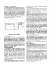
Examination indicates that 16 would be an appropriate
common denominator, allowing the expression to be re-
written as follows:
and simplifying,
Taking the reciprocal of (inverting) the final expression
gives:
16
ZT
=
-
=
5.3 ohms
3
For a series-parallel interconnection of different speaker
impedances, determine the total parallel-connected speak-
er impedance, and add it to the total of series-connected
impedances. The sum is the total load impedance.
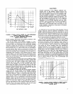
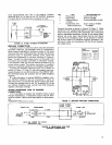
In planning a multiple speaker installation, the maximum
power ratings of the individual speakers being used should
be kept in mind. This is particularly important where speak-
ers of different impedance values are connected to the DI-
RECT OUTPUT Connectors
(8,9). For example, assume an
8-ohm and a 16-ohm speaker are connected in parallel
across the Amplifier output and the Amplifier is operated
at full-rated output. Figure 6, Page 7, shows that approxi-
mately 120 watts are developed across the 8-ohm speaker,
while only 60 watts are produced across the
lgohm
speaker. The power ratings of the speakers employed must
be evaluated accordingly.
70-VOLT OUTPUT
When the 70-volt output of the
SR105A Amplifier is uti-
lized, matching the speaker load to the Amplifier output
impedance is not necessary. The only requirement is that
the total wattage of the speaker load connected to the
70-
volt output does not exceed the power rating of the Ampli-
fier.
In a 70-volt speaker system it is standard practice to cou-
ple each speaker to the 70-volt line with a line transformer.
These transformers are equipped with tapped secondary
windings to accommodate various speaker impedances.
The primary winding is also tapped and labeled with the
wattage rating applicable to each tap. For example, the
Shure
A102A, a 50-watt transformer, has taps at 50, 25, 12
and 6 watts. (Transformers are available at various power
ratings to suit the requirements of the application.) The pri-
mary taps allow adjustment of the power level delivered to
the speaker when the transformer is connected to the
70-
volt line. Connection of the 50-watt tap to the 70-volt line
produces 50 watts across the speaker when the audio
signal level on the line is 70 volts. Similarly, use of the
25-
watt tap produces 25 watts across the speaker.
The total load in watts presented by a 70-volt multiple
speaker system is the sum of the individual speaker loads.
The value of each individual speaker load is indicated by
the wattage rating of the transformer primary tap con-
nected to the 70-volt line. For example, assume only two
speakers are connected to a 70-volt line, the first using a
50-watt primary tap and the second using a 25-watt tap.
The total load across the 70-volt line is therefore 50 plus 25,
or 75 watts.
In the design of sound reinforcement installations, good
engineering practice allows for change or growth. An ex-
ample of this is
a
70-volt installation requiring 300 watts.
This system could be handled by two 70-volt lines of 150
watts each, connected individually to two
SR105A Ampli-
fiers. This system would be operating at full capacity with
no room for expansion. The preferred installation would be
three
70-volt lines of 100 watts each, connected individually
to three
SR105A Amplifiers. This arrangement allows addi-
tions or changes in each 70-volt line of up to 50 watts.
OUTPUT VOLTAGE METER
The OUTPUT VOLTAGE Meter (1) provides a convenient
aid for adjusting and monitoring the Amplifier operating
level. The meter scale is calibrated in percent, with 100%
being equivalent to the maximum output voltage of the
Amplifier, prior to clipping. The performance of the meter
is similar to that of a VU meter and it responds to program
material in a similar manner.
It should be noted that a 100% meter indication repre-
sents a signal level of 28.3 volts rms across the DIRECT
OUTPUT
(8,9). The maximum rated amplifier power output
of 200 watts is obtained only when the total speaker load
is
4
ohms across the DIRECT OUTPUT. With loads other
than
4
ohms, a 100% meter indication represents a lower
power output,
e.g., for a total speaker load of
8
ohms, a
100% reading indicates a power output of
100vvatts. Note
that it is not possible to obtain a greater power output with
this load.
Figure 6 may be used as an approximate guide to the
power indicated by a 100% meter indication for various di-
rect speaker loads. Note that while the meter is calibrated
for 28.3 volts output, the typical output power available is
somewhat higher and is indicated by meter readings
greater than 100%.
In the
SR105A Amplifier,
a
100% indication represents
a signal level greater than 70.7 volts rms across the 70V
OUTPUT Terminals (11). The OUTPUT VOLTAGE Meter
(1) may be recalibrated for a 100% indication with
70.7V
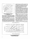
output. Maximum 70-volt amplifier power output is ob-
tained with a 150-watt load (33 ohms) across the 70V
OUTPUT Terminals. Similarly, maximum power output
may be obtained with a combination of direct and 70-volt
loads (see Figure 7, Page 7).
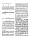
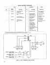
The relationship between the OUTPUT VOLTAGE Meter
(1) reading and the Amplifier direct-coupled output power
is illustrated in the following table: