


in the space exposed by removal of the cover using four
6-32 x
3h1'
Phillips head machine screws. Be sure to orient
the screw contacts on the terminal strip in the same man-
ner as the existing DIRECT OUTPUT terminal strip. Mount
the slide switch next to the terminal strip in the space pro-
vided, using two Phillips round head 4-40 x 3/16" machine
screws. Mount the Filter Circuit board next to the Main
Circuit board using the four 6-32 x
1/4"
Phillips head ma-
chine screws previously used to secure the cover.
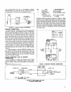
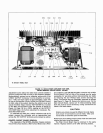
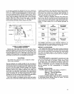
TRANSFORMER
FIGURE
16.
70-VOLT CONVERSION:
TRANSFORMER MOUNTING
Remove the white lead from pin
H
on the Main Circuit
board and fasten it to pin Won the Filter Circuit board. Re-
move the
yellowlblack lead from pin
J
on the Main Circuit
board and fasten it to pin Yon the Filter Circuit board. Cut
a length of 20-gauge hook-up wire
(yellowlblack preferred)
and solder one end to pin
J
on the Main Circuit board.
CAUTION
Be careful not to damage board or adjacent compo-
nents when soldering.
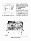
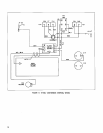
Run the soldered wire roughly parallel to the long edge of
the Main Circuit board to the main wiring harness and along
the harness to the 70-volt slide switch
(S4). Solder the hook-
up wire to the left center terminal (viewed from terminal
side) of the switch (see Figure 17, Page 18). Cut a length of
20-gauge hook-up wire (white preferred) and solder one
end to pin
H
on the Main Circuit board. Run the soldered
wire twice around the two
yellowlblack wires (Main Circuit
board
J
to switch S4, and Filter Circuit board Y to poten-
tiometer
R41) to form a loose shield. Solder the other end of
the white wire to pin
X
on the Filter Circuit board.
Cut three lengths of 20-gauge hook-up wire and solder
them to pins on the Filter Circuit board as follows: from pin
V (yellow preferred) to the upper left (viewed from terminal
side) terminal of switch S4; from pin
T
(blue preferred) to
the bottom left (viewed from terminal side) terminal of
switch S4; and from pin S (red preferred) to the positive
(red dot) terminal of capacitor C14.
Solder a length of 16-gauge hook-up wire (white pre-
ferred) from the 28V terminal of the 28-volt terminal strip
(TS1) to the bottom right (viewed from terminal side) ter-
minal of switch S4 (see Figure 17, Page 18). Solder trans-
former T3 leads coming out of the chassis grommet as
follows:
The Amplifier conversion is now complete. Perform
a
dc
balance adjustment as described previously in this section.
Reassemble the Amplifier and return it to service.
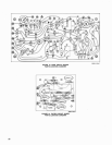
SERVICE ILLUSTRATIONS
The pages that follow contain parts locating drawings
and an overall Circuit Diagram. The parts locating drawings
are of the Main and Filter Circuit boards. Foil circuit paths
are shown as shaded areas on the drawings. The Circuit
Diagram shows all printed circuit board and
chassis-
mounted parts.
GUARANTEE
This Shure product is guaranteed in normal use to be
free from electrical and mechanical defects for a period
of one year from date of purchase. Please retain proof
of purchase date. This guarantee includes all parts and
labor. This guarantee is in lieu of any and all other guar-
antees or warranties, express or implied, and there shall
be no recovery for any consequential or incidental
damages.
SHIPPING INSTRUCTIONS
Carefully repack the unit and return it prepaid to:
Shure Brothers Incorporated
Attention: Service Department
1501 West Shure Drive
Arlington Heights, Illinois 60004
If outside the United States, return the unit to your dealer
or Authorized Shure Service Center for repair. The unit
will be returned
to
you prepaid.
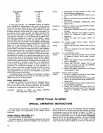
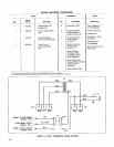
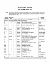
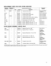
Transformer
Lead Color
Red
Black
Yellow
Green
Blue
Part
Connection
28V Terminal
Strip
(TS1)
70V Terminal
Strip
(TS2)
70V Slide
Switch
(S4)
Part Terminal
Designation
GND
70V
CT
COM
Right Center
Terminal