


2
3
4
5
678910
20
30
40
LOAD IMPEDANCE (OHMS)
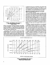
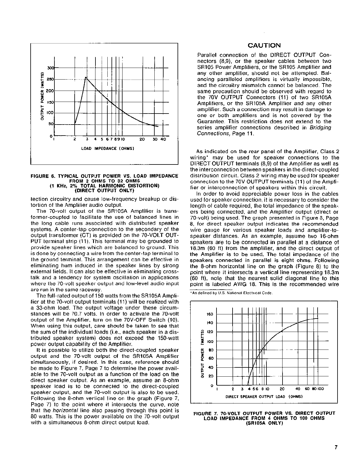
FIGURE
6.
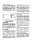
TYPICAL OUTPUT POWER VS. LOAD IMPEDANCE
FROM
2
OHMS TO
32
OHMS
I1 KHz.
2%
TOTAL HARMONIC DISTORTION)
(DIRECT OUTPUT ONLY)
tection circuitry and cause low-frequency breakup or dis-
tortion of the Amplifier audio output.
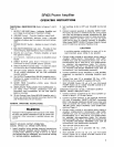
The 70-volt output of the
SRlO5A Amplifier is trans-
former-coupled to facilitate the use of balanced lines in
the long cable runs associated with distributed speaker
systems. A center-tap connection to the secondary of the
output transformer (CT) is provided on the 70-VOLT OUT-
PUT terminal strip (11). This terminal may be grounded to
provide speaker lines which are balanced to ground. This
is done by connecting a wire from the center-tap terminal to
the ground terminal. This arrangement can be effective in
eliminating hum induced in the speaker lines by strong
external fields. It can also be effective in eliminating cross-
talk and a tendency for system oscillation in applications
where the 70-volt speaker output and low-level audio input
are run in the same raceway.
The full-rated output of 150 watts from the
SRI05A Ampli-
fier at the 70-volt output terminals (11) will be realized with
a 33-ohm load. The output voltage under these circum-
stances will be 70.7 volts. In order to activate the 70-volt
output of the Amplifier, turn on the 70V-OFF Switch (10).
When using this output, care should be taken to see that
the sum of the individual loads
(i.e., each speaker in a dis-
tributed speaker system) does not exceed the 150-watt
power output capability of the Amplifier.
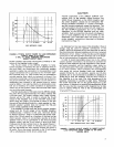
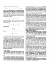
It is possible to utilize both the direct-coupled speaker
output and the 70-volt output of the
SR105A Amplifier
simultaneously, if desired. In this case, reference should
be made to Figure 7, Page 7 to determine the power avail-
able to the 70-volt output as a function of the load on the
direct speaker output. As an example, assume an 8-ohm
speaker load is to be connected to the direct-coupled
speaker output, and the 70-volt output is also to be used.
Following the 8-ohm vertical line on the graph (Figure 7,
Page 7) to the point where it intersects the curve, note
that the horizontal line also passing through this point is
80 watts. This is the power available on the 70-volt output
with a simultaneous 8-ohm direct output load.
CAUTION
Parallel connection of the DIRECT OUTPUT Con-
nectors (8,9), or the speaker cables between two
SR105 Power Amplifiers, or the SR105 Amplifier and
any other amplifier, should not be attempted. Bal-
ancing paralleled amplifiers is virtually impossible,
and the circuitry mismatch cannot be balanced. The
same precaution should be observed with regard to
the 70V OUTPUT Connectors (11) of two
SR105A
Amplifiers, or the SR105A Amplifier and any other
amplifier. Such a connection may result in damage to
one or both amplifiers and is not covered by the
Guarantee. This restriction does not extend to the
series amplifier connections described in Bridging
Connections, Page 11.
As indicated on the rear panel of the Amplifier, Class
2
wiring* may be used for speaker connections to the
DIRECT OUTPUT terminals
(8,9) of the Amplifier as well as
the interconnection between speakers in the direct-coupled
distribution circuit. Class 2 wiring may be used for speaker
connection to the 70V OUTPUT terminals
(1 1) of the Ampli-
fier or interconnection of speakers within this circuit.
In order to avoid appreciable power loss in the cables
used for speaker connection, it is necessary to consider the
length of cable required, the total impedance of the speak-
ers being connected, and the Amplifier output (direct or
70-volt) being used. The graph presented in Figure 8, Page
8, for direct speaker output indicates the recommended
wire gauge for various speaker loads and amplifier-to-
speaker distances. As an example, assume two 16-ohm
speakers are to be connected in parallel at a distance of
18.3m (60 ft) from the amplifier, and the direct output of
the Amplifier is to be used. The total impedance of the
speakers connected in parallel is eight ohms. Following
the 8-ohm horizontal line on the graph (Figure 8) to the
point where it intersects a vertical line representing
18.3m
(60 ft), note that the nearest solid diagonal line to this
point is labeled AWG 18. This is the recommended wire
*As
defined
by
U.S.
National Electrical Code.
160
140
E
120
I-
I-
I
I00
-
f,
80
Z
g
60
I-
2
40
I-
s
20
0
I
2
3
456810 20 40 6080100
DIRECT SPEAKER OUTPUT LOAD (OHMS)
FIGURE 7. 70-VOLT OUTPUT POWER VS. DIRECT OUTPUT
LOAD IMPEDANCE FROM
4
OHMS TO 100 OHMS
(SRIOSA ONLY)