


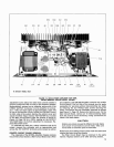


SR105
Power
Amplifier
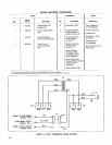
NOTES TO CIRCUIT DIAGRAM
GENERAL
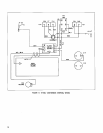
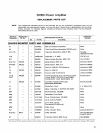
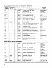
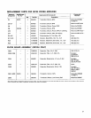
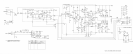
Shure part numbers are not shown in the Parts List
accompanying the Circuit Diagram (Figure 21, Page 25)
if parts are readily available through local electronics parts
suppliers. In these instances, the Circuit Diagram shows
only the reference designation and value of the standard
parts.
All capacitor values are shown in microfarads unless
otherwise designated. All non-electrolytic capacitors are
100 working volts dc or more unless otherwise specified.
Electrolytic capacitors are shown in microfarads
x
volts.
All resistor values are shown in ohms (k
=
1000). Resis-
tors are 10% tolerance unless otherwise specified. Resis-
tors are
Vi-watt unless otherwise specified.
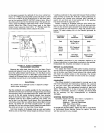
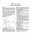
Transistor lead codes are as shown in Figure 20. Accep-
table replacements are as shown in the Parts List.
The following round symbols denote:
Chassis Ground
4
Circuit Ground
&
Printed Circuit Board Ground
A
FIGURE
20.
TRANSISTOR LEAD CODES
TROUBLESHOOTING
A general troubleshooting process is as follows: If the
Amplifier is completely "dead," check the ac power source,
fuses, and power supply output
(52.5V at pin F of Main
Circuit board). If the indicator lamps are on but the output
is distorted, low or not present, apply an input signal as
described under Ac Voltage Measurements below, and
determine that the input and output voltages to each board
assembly are correct. If an incorrect ac voltage is found
at any board output, perform Dc Voltage Measurements on
that board as described below to isolate the problem area.
AC VOLTAGE MEASUREMENTS
The numbers within rectangular symbols
0
on the
Circuit Diagram denote the ac voltage at that point under
the following test conditions:
1. Voltage measured with respect to chassis unless other-
wise indicated.
2. Line voltage:
120V, 50/60 Hz.
3. Test signal of
0.3V, 1 kHz applied across connector J1.
4.
Ac voltage measurements may vary t20% from values
shown.
5. Measurements made with ac VTVM of 1 megohm or
greater input impedance.
6. Four-ohm non-inductive 200-watt load across DIRECT
OUTPUT Terminal Strip
TS1 for direct output measure-
ments or
(SR105A only) 33-ohm non-inductive 150-watt
load across 70-volt OUTPUT Terminal Strip TS2
(70V-
COM) for 70-volt output measurements, but not both.
7. Volume Control set to maximum (10).
8.
SR105A Only: 70V-OFF Switch set to OFF for all circuit
measurements except 70-volt circuitry (Filter Circuit
board and associated components). Filter Circuit board
rolls off the low frequencies; amplifier output should
be -3
-c-1 dB at 30 Hz referenced to
1
kHz and -12
-c-3 dB at 20 Hz.
DC VOLTAGE MEASUREMENTS
The numbers within elliptical symbols
0
on the circuit
diagram denote the dc voltage at that point under the
following test conditions:
1. Voltages measured with respect to chassis unless other-
wise indicated.
2. Line voltage:
120V, 50160 Hz.
3. No input signal applied.
4.
Dc voltage measurements may vary t20% from values
shown.
5.
Measurements made with VTVM of 11 megohms or
greater input impedance.
RESISTANCE MEASUREMENTS
With the ac line cord disconnected from the ac source
and the POWER ON-OFF Switch in the OFF position, the
following ohmmeter measurements may be made:
1. Transformers may be checked for continuity of each
winding.
2. To test transistors and diodes, see Page 15.