


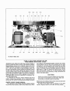


SR105
Power Amplifier
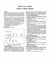
CONDENSED OPERATING INSTRUCTIONS
DIRECT SPEAKER OUTPUT
(MODELS SRlOSA and SRlOSBI
CONSTANT VOLTAGE 70-VOLT SPEAKER OUTPUT
(MODEL
SRlOSA ONLY)
I.
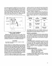
'with line cord unplugged, install Amplifier in rack or
l.
Amplifier
and
connect
auxiliary
equipment
as
carrying case, allowing adequate ventilation.
2. Connect speakers to DIRECT OUTPUT Jacks
and/or
for Direct Speaker Output operation.
Terminal
Stri~. 2. Connect speakers to 70V OUTPUT Terminal Strip.
3. Connect
con'sole or mixer output to UNBALANCED
3. Connect console or mixer output to UNBALANCED
PARALLELED
HIGH IMPEDANCE Input Jack. For cable
PARALLELED
HIGH IMPEDANCE Input Jack. For cable
length greater than
15m (50 ft), use 600-ohm bat- length greater than 15rn (50
ft),
use 600-ohm bal-
anced line into BALANCED BRIDGING
Input Jack anced line into BALANCED BRIDGING Input Jack
(three-pin). (three-pin).
.
.
4.
connect additional power amplifiers or auxiliary equip-
4.
fur,
70V-OFF
Switch
to
70".
ment as required.
5. Connect line cord to ac source.
5. Connect line cord to ac source.
6.
Turn on POWER ON-OFF Switch and adjust VOLUME
6. Turn POWER ON-OFF Switch on and adjust VOLUME
Control to desired level. Control.
SR105
Power Amplifier
ARCHITECTS' AND ENGINEERS' SPECIFICATIONS
SRlOSA POWER AMPLIFIER
The Amplifier shall be a rack-mounted, 120-volt,
50/60
Hz line-operated, all silicon transistor, 200-watt power
amplifier.
The Amplifier shall
deliver 200 watts rms continuous out-
put power at
1
kHz into a 4-ohm load with less than
2%
distortion (DIRECT OUTPUT), and 150 watts rms continuous
output power with less than 3% distortion to a 33-ohm load
(70-VOLT OUTPUT). Typical frequency response shall be
20 to 20,000 Hz
t1.5 dB with a 4-ohm load (DIRECT OUT-
PUT) and 50 to 15,000 Hz 2 db with a 33-ohm load
(70-
VOLT OUTPUT).
The Amplifier
shall have four phone jacks and one ter-
minal strip speaker output for
25-volt output, plus one ter-
minal strip for 70-volt output.
The Amplifier shall have
built-in circuitry to protect the
Amplifier from open circuit, short circuit, or mismatched
output loads, by using current-limiting, voltage-limiting,
temperature-sensing diodes, and thermal-sensing switches.
The automatic thermal-sensing switches and temper-
ature-sensing diodes shall be mounted on the output tran-
sistor heat sinks to protect the Amplifier from overheating
due to short circuits, mismatched output loads, or high
ambient temperatures. The thermal switches shall auto-
matically shut off the ac power in the event of overheating
and shall automatically restore the ac power when the
Amplifier has reached a safe operating temperature. When
the Amplifier has thermally cycled off, a THERMAL
OVER-
LOAD indicator shall light.
The INPUTS shall accept signals from high impedance
sources. The balanced bridging input shall be a profes-
sional three-pin audio connector. The unbalanced input
connectors shall be standard
%-inch phone jacks.
The Amplifier shall have an independent VOLUME con-
trol, POWER ON-OFF Switch and
70-VOLTIOFF Switch
to activate the 70-volt output transformer.
The Amplifier shall be enclosed in a metal, rack-mount-
ing cabinet, with a scuff-resistant vinyl-covered front panel.
The dimensions shall be 178 mm
x
483 mm x 270 mm
(7 inches in height, 19 inches in width, and
lO5/8
inches
in depth). The weight shall be no more than 15.66 kg
(34
pounds 8 ounces).
The Amplifier shall have a maximum voltage gain of
27
-+2 dB at 1 kHz, and a nominal input sensitivity of
1.2 volts for 200 watts rms output power to a 4-ohm load.
Seventy-volt circuitry voltage gain shall be 35
%3.5 dB
at 1 kHz, and a 1.2-volt
nominal input sensitivity for 150
watts rms output power to a 33-ohm load.
The
Amplifier hum and noise shall be at least 80 dB
below 200 watts rms output with a 4-ohm resistive load.
The Amplifier
shall contain 4 silicon output transistors,
13 other
silicon transistors, and 1 Zener diode.
Any Amplifier not meeting all of the above specifications
shall be deemed unacceptable under this specification.
The Amplifier shall be a Shure Model
SR105A.
SRlOSB
POWER AMPLIFIER
The Amplifier shall be a rack-mountable, 120-volt,
50/60
Hz line-operated, all silicon transistor, 200-watt powar
amplifier.
The Amplifier shall deliver 200 watts
rms continuous
power at 1 kHz into a 4-ohm load with less than 2% dis-
tortion. Typical frequency response shall be 20 to
20,DOO Hz
21.5 dB with a 4-ohm load.
The
Amplifier shall have four phone jacks and one ter-
minal strip speaker output for 25-volt output.