


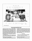
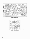

OUTPUT TRANSISTORS
Output transistors
Q9 through Q12 (Figure 13, Page 13)
are located on the black, finned heat sinks. The replace-
ment procedure is the same as that used for driver tran-
sistors Q7 and Q8.
NOTE: Output transistors
Q9 through Q12 must be
matched for current gain. When replacing output transis-
tors, be sure to replace with devices which have the same
gain and part number as the original transistors. Shure
transistors have a letter suffix in the part number
(i.e.,
86A360A)
which serves as a gain code. Transistors with the
same part number and suffix letter have equal current gain.
DIODES
Diodes
Dl5 and Dl6 (Figure 13, Page 13) are located on
the black, finned sinks with the output transistors. Special
care is required to insulate these diodes from the heat sink
while providing good heat transfer from sink to diode.
Heat-
shrinkable tubing or "spaghetti" should be placed over the
diode and connecting leads; the diode should be securely
clamped to the heat sink with the clamp provided.
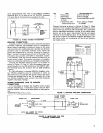
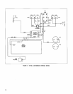
DIODE BRIDGE RECTIFIER
Silicon diode bridge rectifier
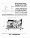
Dl1 is mounted on the
underside of the chassis as shown in Figure 14, Page 14.
When replacing this component, apply Wakefield Type 120
thermal joint compound between the heat sink base of the
rectifier and the chassis to provide good heat transfer to
the chassis. Note that the base of the rectifier is provided
with a locating pin. When installing the rectifier be sure
to position it such that the locating pin fits into the hole
provided for it in the chassis. The terminals are marked to
indicate the ac connections to the power transformer and
the
(+)
and
(-)
dc output connections to filter capacitors
C14 and
C15.
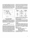
CHECKING TRANSISTORS AND DIODES
Defective transistors and diodes may be located by use
of a standard ohmmeter such as a
Simpson Model 260.
(Polarity of the ohmmeter must be verified before these
checks are made.)
With a known diode orientation, measure the diode re-
sistance in the forward and reverse directions. The lowest
meter reading establishes the probe at the cathode end
(schematic symbol arrow points to cathode) as the "minus"
probe while the other probe is "plus." Some ohmmeters
are not polarized in this manner with relation to "volts
plus probe" and "volts minus probe." With the ohmmeter
"plus" probe on the anode end of a diode and the "minus"
probe on the cathode end, the ohmmeter should read ap-
proximately 2
kilohms or less. With the meter probes
reversed, a reading of about 10 kilohms or more should
occur. If either of these conditions is not met, the diode
should be replaced.
When checking the bridge rectifier disconnect all leads
to the assembly, noting the terminals to which they were
connected. Check each diode leg of the bridge in the same
manner as described previously for individual diodes. Refer
to the preceding section, Diode Bridge Rectifier, for instal-
lation instructions if replacement is required.
To check transistors, the ohmmeter should be set to the
100- or 1,000-ohm scale. Small signal transistors
(Q1
through Q6, Q13, (214, Q201 through (2203) must be re-
moved from the circuit before testing. Transistors mounted
with screws (Q7 through Q12) may be tested in place; how-
ever, the base and emitter leads to these transistors must
be removed.
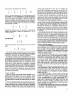
If all conditions in the following table are met, the tran-
sistors may be considered free of any major defect; if any
of the following conditions are not met, the transistor
should be replaced. See Notes to Circuit Diagram (Figure
20, Page 23) for transistor terminal codes.
Ohmmeter Connections
"Plus" Lead "Minus" Lead
Collector Emitter
Emitter Collector
Collector Base
Emitter Base
Base Collector
Base Emitter
Ohmmeter Reading
NPN PNP
Transistor Transistor
High High
High High
High Low
-
Low
Low High
Low
-
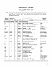
SR105B AMPLIFIER CONVERSION FOR
70-VOLT OUTPUT
If it becomes necessary to equip a Model
SRIOSB Power
Amplifier for 70-volt output (distributed speaker) operation
in addition to the existing 28-volt direct output, the conver-
sion may be accomplished using the parts and procedures
described below. The required parts may be ordered
through a local Shure Franchised Dealer or directly from
the Shure Factory. No modifications to the metal chassis or
front panel are required.
WARNING
This conversion should only be performed by quali-
fied service personnel or the Shure Factory Service
Department.
Once the conversion is performed, the Amplifier is identical
to the
SR105A Amplifier and all instructions and diagrams
pertaining to the
SR105A Amplifier apply.
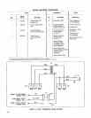
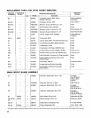
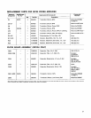
The following parts, materials and tools are required to
perform the 70-volt conversion (NOTE: Figure 15, Page 16
shows the electrical circuitry involved. Reference to the
SR105A Amplifier Circuit Diagram, Figure 21, Page 25, will
aid in understanding the circuit modifications.)
Remove the line cord from the ac outlet and remove all
input and output cables. Remove the metal grille cover as
described previously in this section. Remove the two lock-
nuts securing the two lamp socket assemblies (see Figure
16, Page 17). Remove the lamp socket assemblies from the
mounting studs and move them away from the studs to
permit mounting of the 70-volt transformer. Place the trans-
former over the four mounting studs, orienting the trans-
former leads toward the center of the Amplifier chassis.
Replace the lamp socket assemblies, orienting them as
shown in Figure 16, and secure the transformer using the
two locknuts previously removed and the two supplied with
the transformer. Pass the transformer leads through the
unused grommet nearest the rear of the Amplifier chassis.
Turn the Amplifier upside-down and remove the chassis
bottom plate as described previously in this section. Re-
move the rear-panel 70-volt conversion Cover (marked
SHURE MODEL
SRlO5B) (MP6) by removing the four
screws securing it to the chassis. Mount the terminal strip