


Main Circuit Board
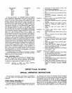
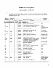
SMALL SIGNAL AND PREDRIVER TRANSISTORS
Transistors
Q1
through
Q6, Q13, Q14,
and
Q201
through
Q203
are mounted on printed circuit boards. When re-
placing these transistors it is imperative that proper lead
configuration be followed. A minimum of soldering heat
should be used to avoid damage to the transistor or printed
circuit board. Refer to the Notes to Circuit Diagram (Figure
20,
Page
23)
for the transistor lead codes.
Letter
A
B
C
D
E
F
G
H
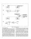
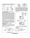
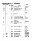
DRIVER TRANSISTORS
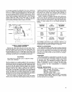
Driver transistors
Q7
and
Q8
(Figure
13,
Page
13)
are
mounted on a bracket located on the top surface of the
Amplifier chassis. Before removing these transistors, write
down the lead color and location at each transistor solder
junction. When replacing transistors, apply Wakefield Type
120
thermal joint compound to each side of the insulating
wafer to provide good heat transfer from transistor to
bracket. After replacement and before connecting transis-
tor leads, check the transistors between case and chassis
with an ohmmeter; there should be no continuity. Be sure
that these transistors are not interchanged in the circuit;
they are not identical devices.
Q7
is an NPN transistor and
Q8
is a PNP transistor. Refer to the Notes to Circuit Diagram
(Figure
20,
Page
23)
for the transistor lead codes.
;
"
1;
2;"
Yellow Yellow/Black
-
-
-
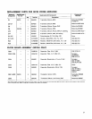
NOTE: Production variations may result in wire colors dif-
fering from those in the table.
Filter Circuit Board
Wire Color
Blue
Black
Gray
Green/Black
Violet
Red
White
White
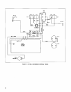
R45 R46 R30 J6
W
I
F2
(XF2)
F
I
TI
F3
R4
841
Al
R27 PLI R37 C14
C15
R3
MPI M P4
DII MP5
*
SR105A MODEL ONLY
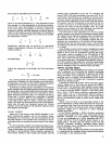
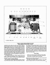
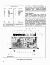
FIGURE 14. SR105 POWER AMPLIFIER BOTTOM VIEW,
COVER REMOVED
(SR105A MODEL SHOWN)
Letter
J
K
L
M
N
P
R
Wire Color
Yellow/Black
Orange/Black
Orange
Brown
Yellow
Green
White