56
SD-AS10
Advanced Features
- Connecting other equipment -
Connecting other equipment
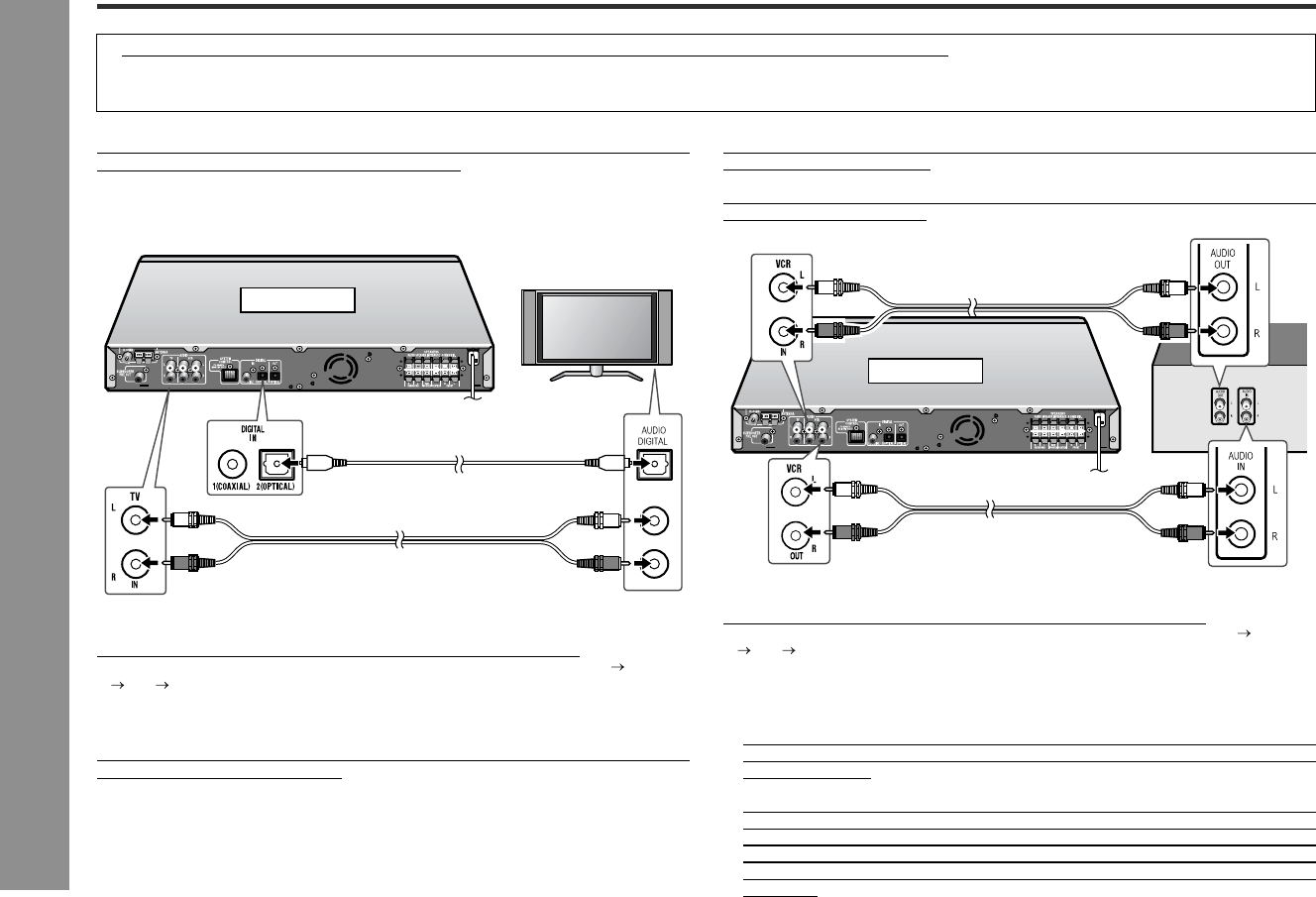
" Audio connection to TV
You can listen to TV sound from the speakers by connecting the amplifier unit using
an optical digital cable or audio cable (not supplied).
To listen to TV sound:
Turn the power on and press the FUNCTION button on the main unit.
Each press of this button changes the input in the order of "DIGITAL 1" "DIGITAL
2" "TV" "VCR".
You can also use the DIG FUNCTION (DIGITAL 1/DIGITAL 2) or FUNCTION (TV/
VCR) button on the remote control.
" Audio connection to VCR
You can listen to VCR sound from the speakers by connecting the amplifier unit using
an audio cable (not supplied).
To record sound from the main unit, connect the VCR audio output jacks (amplifier)
with audio input jacks (VCR).
To listen to VCR sound:
Turn the power on and press the FUNCTION button on the main unit.
Each press of this button changes the input in the order of "DIGITAL 1" "DIGITAL
2" "TV" "VCR".
You can also use the FUNCTION (TV/VCR) button on the remote control.
Notes:
! The audio VCR output jacks sends signals coming from a DVD/CD, the tuner,
audio TV input jacks and digital audio input jack. Signals from the audio VCR input
jacks are not sent.
! When sending signals coming from the digital audio input jack via the audio VCR
output jacks on the unit, set the stereo mode to STEREO (see page 41). In the
multi channel mode, signals may not be sent properly. When sending signals from
the digital audio input jack to the audio VCR output jacks, the audio output level
decreases. (Leave headphones unplugged while recording to avoid further level
decrease.)
Turn off the other equipment before making this connection.
! An optical digital cable, audio digital cable and audio cable are not included. Purchase a commercially available cable.
! If using an audio cable, purchase one without resistance. If you use an audio cable with resistance, sound volume will decrease.
! Plug in each cable fully to prevent noise interference.
DIGITAL 2: The audio input is switched to "OPTICAL".
TV: The audio input is switched to "ANALOG 1".
Optical digital cable
(commercially available)
To optical digital
audio output jack
TV
L
R
AUDIO OUT
Audio cable
(commercially available)
To audio
output jacks
Amplifier unit
VCR: The audio input is switched to "ANALOG 2".
VCR
Amplifier unit
Audio cable
(commercially available)
To audio
input jacks
Audio cable
(commercially available)
To audio
output jacks
