


WWW.POLKAUDIO.COM/AMPS
17
16
PA 12V AMPLIFIERS
ENGLISH
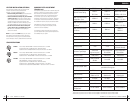
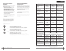
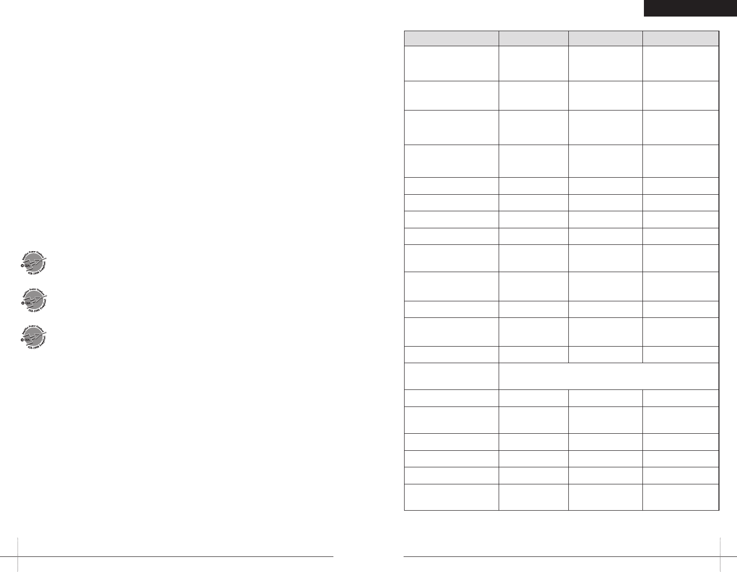
SPECIFICATIONS
PA200.4 PA500.4
PA1100.5
Dynamic Power Rating
80W x 4
@2Ohms
200W x 4
@ 2 Ohms
200W x 4 @ 2 Ohms
1200W x 1 @ 1 Ohm
RMS Continuous Power
Bridged @ 4 Ohms
100W x 2 250W x 2
250W x 2
600Wx1@1Ohm
RMS Continuous Power
@ 2 Ohms
2
50W x 4 125W x 4
125W x 4
600Wx1@1Ohm
RMS Continuous Power
@ 4 Ohms
1
35W x 4 90Wx4
80W x 4
280W x 1
Conversion Efficiency >66% @ 4 ohms
>66% @ 4 ohms
Frequency Response 20Hz-20kHz 20Hz-20kHz
20Hz-20kHz
Signal to Noise Ratio >90dBA >98dBA
>98dBA
Separation 65db @ 1kHz 65db @ 1kHz
65db @ 1kHz
Damping Factor >100 >150
>150
(>50 sub channel)
Crossover Type/Range
Switchable
high or low pass
2-way Butterworth
50 to 500Hz
2-way Butterworth
50 to 500Hz
Crossover Slope 12dB/octave 12dB/octave
12dB/octave
Bass Equalization
+8dB, centered
@40Hz
0to+8dB
0to+8dB
Subsonic Filter
Variable
RCA Input/Output Jacks
2-channel in/2-channel
paralleled full range out
Input Impedance 20K ohms 20K ohms
20K ohms
Input Sensitivity
Variable from
250mV to 7.5V
Variable from
250mV to 8V
Variable from
250mV to 8V
Supply Voltage 10-16VDC 10-16VDC
10-16VDC
Fusing/Type 1x30A 2x40A
3x40A
Minimum Cable Required
#10 #8 #8
Port Output (Optional Fan)
LED(Optional)
12V @ <200mA 12V @ <200mA 12V @ <200mA
1
RMScontinuouspower driveninto 4Ohms from20 to20,000 Hz@ 14.4VDCwith lessthan 0.08%THD+N.
2
RMScontinuouspower driveninto 2Ohms from20 to20,000 Hz@ 14.4VDCwith lessthan 0.15%THD+N.
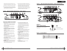
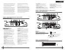
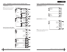
LED TUBE INSTALLATION (OPTIONAL)
ThesePolkAudio amplifiershave beendesigned with
acustomheat sinkthat canaccommodate two
(optional—notsupplied)VARAD LEDtubes.
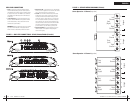
1.Before installingthe LEDtubes, removeand discard
themountingfeet fromthe VARADLED tubes.
2.Slide eachLED tubeassembly intoyour PolkAudio
amplifierheatsink. Ensurethat theLEDs arefacing
outforoptimal visibility.The wiresfrom theLED tube
assemblyshouldbe onthe signalinput endof the
amplifier.TheBlack wirefrom theLED tubeis ground
andtheBlack/White wirefrom theLED tubeis power.
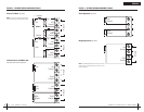
3.Run thetwo wiresfrom thetube assemblyand
connectthemto the4-pin LED/FANinput connec-
tor.Referto theLED/FAN harnessdiagram given
earlierinthis manual.
NOTE:Ifthe optionalfan ISNOT beingused, werecom-
mendthatthe secondLED tubebe wiredto thiscircuit.
Iftheoptional fanis beingused, werecommend thatthe
secondLEDtube bewired inparallel withthe firstLED tube.
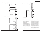
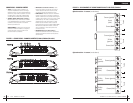
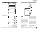
SUBSONIC FILTER ADJUSTMENT
(PA1100.5 only)
Thisamplifieruses asubsonic filterto maximizethe perfor-
manceofa subwoofer.The subsonicfilter isa high-pass
filterthatremoves unwantedbass outputat verylow
frequenciesformthe woofer.This increasesthe output
ofasubwoofer byas muchas 3dB byincreasing the
mechanicalpowerhandling ofthe subwoofer.Depending
onthetype ofenclosure thesubsonic filtercan increase
theuseablelow frequencyoutput byan additional10dB!
Acceptableboostlevels aredetermined bythe type
ofenclosureused, wattageof theamplifier, andthe
subwoofer’sexcursioncapability.
Thefollowingguidelines shouldbe usedfor properset
upofthe subsonicfilter toprovide optimumperformance
andreliabilityfrom yoursystem.
PA200.4 PowerOutput:45 WattsRMSx4channelsat4 Ohmsand ≤1% THD+N
SignaltoNoise Ratio:-80 dBA(reference 1Watt into4 Ohms)
AdditionalPower:50 WattsRMS x4 channelsat 2Ohms and≤ 1%THD+N
PA500.4 PowerOutput:90 WattsRMS x4 channelsat4Ohms and≤ 1%THD+N
SignaltoNoise Ratio:-81 dBA(reference 1Watt into4 Ohms)
AdditionalPower:125 WattsRMS x4 channelsat 2Ohms and≤ 1%THD+N
PA1100.5 PowerOutput:80 WattsRMSx4channelsat4 Ohmsand ≤1% THD+N
280WattsRMS X1 channelat 4ohms ≤1%THD+N
SignaltoNoise Ratio:-80 dBA(reference 1Watt into4 Ohms)
AdditionalPower:125 WattsRMS x4 channelsat 2Ohms ≤ 1%THD+N
AdditionalPowerSubchannel: 600WattsRMS x1 channelat 1Ohm≤1% THD+N
CEA SPECIFICATIONS