


WWW.POLKAUDIO.COM/AMPS
9
8
PA 12V AMPLIFIERS
ENGLISH
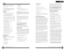
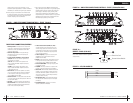
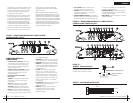
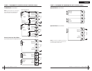
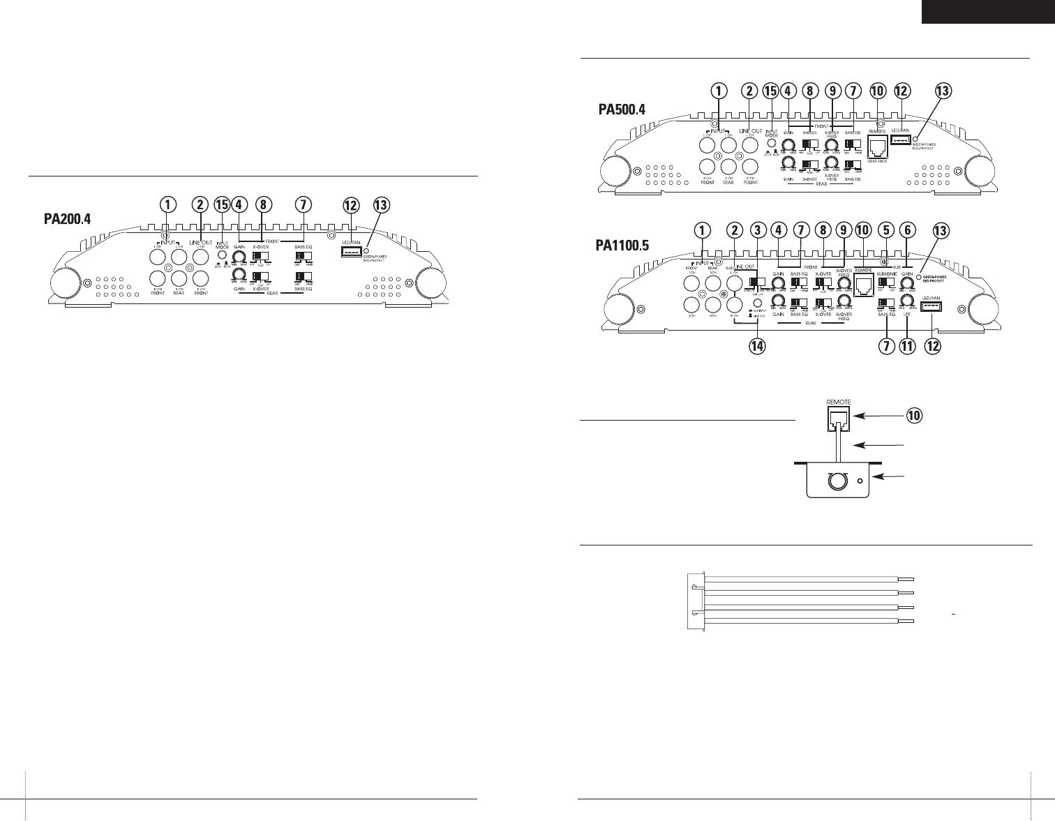
FIGURE 1a—AMPLIFIER CONNECTIONS/CONTROLS—FRONT (PA500.4/PA1100.5)
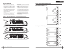
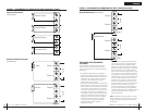
FIGURE 2—LED/FAN HARNESS
BLACK
BLUE
BLACK
RED
-
+
-
+
TOLEDs
TOF AN
FRONT PANEL CONNECTIONS/CONTROLS
1.RCA InputJacks—Accepts linelevel outputsfrom
headunitsor signalprocessors atvoltages between
250mVand7.5 volts.(The PA500.4and PA1100.5
alsohavea RearInput.)
2.RCA LineOutput Jacks—Thesepass-through
RCAjackscan beused tosend theinput signal
toasecond amplifier.
3.Line OutSwitch (PA1100.5)—threepositions:
sumL/R—leftfront andrear andright frontand
rearchannelsare summed.
subL+R—setthe switchto thisposition when
usinganadditional PA600.1amplifier connected
inParallelmode.
sub180—setthe switchto thisposition when
usinganadditional PA600.1amplifier connected
inExternalBridge mode.
4.Gain Control—Controlsthe amplifier’ssensitivity
andisused tomatch theinput levelof theamplifier
totheoutput levelof thesignal source(front and
rearonPA500.4 andPA1100.5).
5.Subsonic Switch—TheOFF positiontakes thefilter
outofthe system,the INposition placesthe filterinto
thesystem(PA1100.5).
6.Sub Gain—–Subwoofer channelgain adjustment.
7.Bass EQSwitch—Adds 8dBadditional bassboost
(PA200.4andPA500.4). Allows8db additionalbass
boostonthe subchannel (PA1100.5).
8.X-Over SelectionSwitch (HPF,Flat, LPF)—
TheHPFattenuates lowfrequencies andis used
withmid-rangespeakers andtweeters. Flatdoes
notattenuateany frequenciesand isfor fullrange
speakersystems.LPF attenuateshigh frequencies
andisused forsubwoofers.
9.X-Over Frequency—adjuststhe crossoverpoint
(50-500Hz)forthe on-boardactive crossover
(PA500.4andPA1100.5).
10.Remote—Optionalaccessory whichallows thelevel
tobeadjusted remotely(usually locatedfor control
bythevehicle’s driver).(PA500.4 andPA1100.5)
11.LPFControl(PA1100.5)—Sets highfrequency limit
ofsubwooferchannel.
12.LED/FAN—Allowsconnection ofan optionalLED
lightbaror optionalcooling fanfor theamplifier.
13.StatusLED—Will illuminateGREEN toindicate the
amplifierison andoperating normally,and willbe
illuminatedREDif theamplifier shutsdown dueto
shortcircuit,DC offset,or overheatingdetected by
onboardprotectioncircuitry.
14.SubInput/Line Out—selectsRCA jacks(4) (Sub/
LineOut)as eitherSubwoofer Inputor LineOutput
(PA1100.5).
15.InputMode Switch—Selects2 or4 channel
operation(PA200.4and PA500.4).
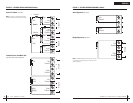
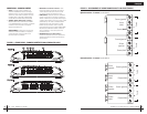
FIGURE 1—AMPLIFIER CONNECTIONS/CONTROLS—FRONT (PA200.4)
speakerload,the moreheat isgenerated. Forlow-
impedancespeakerapplications orrestricted ventilation
installations,anexternal coolingfan maybe advisable.
10.Batteryand groundconnections tothe vehicleshould
bemadewith crimpedring terminalsof theappropriate
size(surfacearea iswhat counts;)soldering thetermi-
nalsaftercrimping isalso recommended.
11.Dueto thehigh-frequency MOSFETswitching power
supply,filteringthe powercable isnot generallyrequired
(rememberthatthe ampcan’t deliverfull outputif the
powersupplyis restricted).Proper groundingof the
signalsourceis mandatoryfor theamplifier toreach
itsperformancepeak. Ifthe RCAinputs arenot grounded
adequatelyviathe signalsource, electricalnoise from
thevehiclemay bepicked upin thesystem.
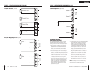
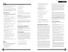
FIGURE 1b—
REMOTE (PA500.4/PA1100.5)
Remote—Controlsthesubwoofer amplifiergain,
fromaremote locationfor easeof adjustment
duringlistening.
Phone Line Cord
Remote Volume Module