


WWW.POLKAUDIO.COM/AMPS
11
10
PA 12V AMPLIFIERS
ENGLISH
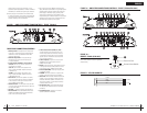
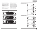
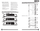
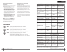
Stereo Operation—2 Channel (top view)
Stereo Operation—4 Channel (top view)
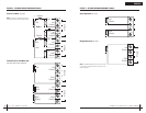
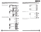
FIGURE 4—SPEAKERWIRINGDIAGRAMS(PA200.4)
Bridged Bridged
LCH
RCH
LCH
RCH
FRONT
(LEFT)
REAR
(LEFT)
REAR
(RIGHT)
FRONT
(RIGHT)
BridgedBridged
LCH
RCH
LCH
RCH
FRONT
(RIGHT)
REAR
(LEFT)
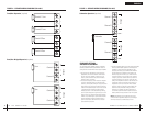
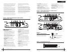
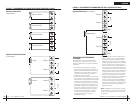
REAR PANEL CONNECTIONS
1.Fuses—These fusesprotect theamplifier against
internalelectricaldamage andare meantto protect
theamplifieronly. Allother powerconnections should
befusedat thesource. ThePA200.4 uses1-30A fuse,
thePA500.4uses 2-40Afuses andthe PA100.5uses
3
-40Afuses.
2
.(+) 12Volt Power—Connectthis terminalthrough
aFUSEor CIRCUITBREAKER tothe positiveterminal
ofthevehicle batteryor thepositive terminalof an
isolatedaudiosystem battery.
WARNING:Alwaysprotect thispower wireby install-
ingafuse orcircuit breakerof theappropriate size
within12inches ofthe batteryterminal connection.
3.Remote TurnOn—This terminalturns onthe amplifier
when(+)12 voltis appliedto it.Connect itto theremote
turnonlead ofthe headunit orsignal source.
4.Ground—Connect thisterminal directlyto thesheet
metalchassisof thevehicle, usingthe shortestwire
necessarytomake thisconnection. Alwaysuse wire
ofthesame gaugeor largerthan the(+) 12volt power
wire.Thechassis connectionpoint shouldbe scraped
freeofpaint anddirt. Useonly qualitycrimped and/or
solderedconnectorsat bothends ofthis wire.DO NOT
connectthisterminal directlyto thevehicle battery
groundterminalor anyother factoryground points.
5.Speaker Terminals—Connectsubwoofers tothese
terminals.(Referto theSpeaker WiringDiagrams
sectionofthis guide.)
FIGURE 3—AMPLIFIER CONNECTIONS—REAR (PA200.4/PA500.4/PA1100.5)
Bridged
Left
Channel
Right
Channel
Bridged
Bridged
Bridged
Front
(Right)
Rear
(Left)
Left
Channel
Right
Channel
Front
(Left)
Front
(Right)
Rear
(Left)
Rear
(Right)
Left
Channel
Right
Channel
Left
Channel
Right
Channel