


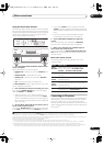
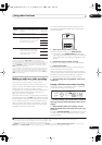

Other Settings
09
63
En
Chapter 9:
Other Settings
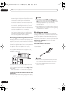
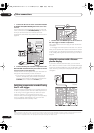
The Input Setup menu
You only need to make settings in the Input Setup menu
if you didn’t hook up your digital equipment according to
the default settings (see
Input function default and
possible settings
below). In this case, you need to tell the
receiver what equipment is hooked up to which terminal
so the buttons on the remote correspond to the
components you’ve connected.
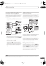
1 Switch on the receiver and your TV.
Use the
RECEIVER
button to switch on.
2 Press
RECEIVER
on the remote control, then press
the
SETUP
button.
An on-screen display (OSD) appears on your TV. Use the
///
buttons and
ENTER
to navigate through the
screens and select menu items. Press
RETURN
to
confirm and exit the current menu.
3 Select ‘Input Setup’ from the System Setup menu.
4 Select the input function that you want to set up.
The default names correspond with the names next to the
terminals on the rear panel (such as
DVD/LD
or
VIDEO
1/GAME 1
) which, in turn, correspond with the names
on the remote control.
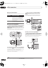
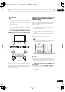
5 Select the input(s) to which you’ve connected your
component.
For example, if your DVD player only has an optical
output, you will need to change the
DVD/LD
input
function’s
Digital In
setting from
COAX 1
(default) to the
optical input you’ve connected it to.The numbering
(
OPT1
–
4
) corresponds with the numbers beside the
inputs on the back of the receiver.
• If you change the setting to an input that has been
previously assigned to another function (for example,
SAT
) then the setting for that function will
automatically be switched off.
• If you used component video cords to connect your
component you must tell the receiver which input
you connected it to, or else you may see the S-video
or composite video input instead of the component
video signal.
1
• If you have more than one iLINK component
connected, you can assign each one to a different
input function in the same way (to check your
settings after doing so, see
Checking the i.LINK
inputs
on page 52).
2
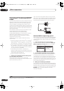
6 When you’re finished, select ‘Next’ to continue to
the next screen.
The second screen of the Input setup has three optional
settings:
•
Input name
– You can choose to rename the input
function for easier identification. Select
Rename
to
do so, or
Default
to return to the system default.
SLEEP
ANALOG
VIDEO
RECEIVER SOURCE
SYSTEM OFF
INPUT
SELECT
DVD SAT
VIDEO 1 T V CONT
DVR1 i Pod
TUNER
RECEIVER
CD
DVR2
CD-R
TV VIDEO 2
XM RADIO
ROOM2/3
+
10
DISC
CLASS
D.ACC ES S
ENTER
TV CONTROL
VOL
TUNE
TUNE
ST ST
TV CH
INPUT
SELECT
TV VOL
ENTER
AV PARAMETER
TOP MENU ì
DTV MENU
CH LEVEL
MENU
T.EDIT
BAND
GUIDE
RETURNRETURN
SETUPSETUP
CATEGORY
ì
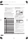
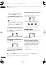
System Setup
1.Auto MCACC
2.Surr Back System
3.Manual MCACC
4.Data Management
5.Manual SP Setup
6.Input Setup
7.Other Setup
: Exit
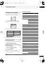
6.Input Setup (1/2)
Input DVD
Digital In [ COAX-1 ]
HDMI Input [ Input-2 ]
Component In [ Comp-2 ]
S-Video In [ Input-1 ]
i.LINK In
[ DV-S969A ]
( Next )
:Finish
Note
1 For high-definition video (using component video connections), or when digital video conversion is switched off (in
Setting the AV options
on page 66),
you must connect your TV to this receiver using the same type of video cable as you used to connect your video component.
2• If you assign i.LINK-equipped components to an input (for example
DVD/LD
), you will be able to select both audio and video signals from i.LINK-
equipped components using the corresponding input source button (or the
INPUT SELECT
button /
INPUT SELECTOR
dial). Assigning i.LINK sources also
allows you to keeps the sound settings you’ve made for other input functions.
• An i.LINK-equipped video component should be assigned to the input function to which you have connected the video signal from the component.
• If you assign an i.LINK input to a certain function (for example
DVD/LD
) then any digital inputs previously assigned to that function will automatically
be set to
i.LINK
(not assigned).
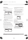
6.Input Setup (1/2)
Input DVD
Digital In [ COAX-1 ]
HDMI Input [ Input-2 ]
Component In [ Comp-2 ]
S-Video In [ Input-1 ]
i.LINK In
[ DV-S969A ]
( Next )
:Finish
6.Input Setup (2/2)
( Back)
TV Game
Input Name Default
12V Trigger1 [ M.ROOM ]
12V Trigger2 [ ROOM 2 ]
PDP In (SR+) [ Input-1 ]
:Finish
ENTER : Next
VSX_84TXSi.book.fm 63 ページ 2006年3月13日 月曜日 午前11時54分