


Connecting your equipment
03
19
En
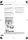
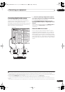
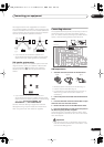
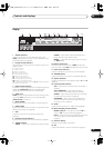
The diagrams below show suggested surround and
surround back speaker orientation. The first diagram (
fig.
A
) shows orientation with one surround back speaker (or
none) connected. The second (
fig. B
) shows orientation
with two surround back speakers connected.
• If you have two surround back speakers THX
recommends placing them together and the same
distance from your listening position (see below).
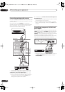
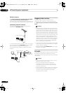
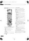
THX speaker system setup
If you have a complete THX speaker system, follow the
diagram below to place your speakers. Note that the
surround speakers ( indicates bi-polar radiating
speakers) should output at an angle parallel to the
listener.
• If you have two surround back speakers THX
recommends placing them together and the same
distance from your listening position for the following
THX modes:
THX Select2 CINEMA
,
THX
MUSICMODE
and
THX GAMES MODE
.
See also
THX Audio Setting
on page 46 to make the
settings that will give you the best sound experience
when using the Home THX modes (on page 28).
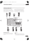
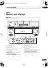
Connecting antennas
The supplied antennas provide a simple way to listen to
AM and FM radio. If you find that reception quality is
poor, an outdoor antenna should give you better sound
quality—see
Connecting external antennas
below.
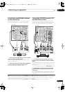
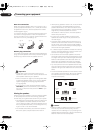
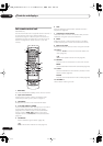
AM loop antenna
1 Assemble the stand as shown in the illustration.
• Bend the stand in the direction indicated (fig. A).
• Clip the loop into the stand (fig. B).
• It’s possible to fix the AM antenna to a wall (fig. C).
Before fixing, make sure that the reception is
satisfactory.
2 Pull off the protective shields of both AM antenna
wires.
3 Press the
AM LOOP
antenna terminal tabs to open
and insert one wire into each terminal.
4 Release the tabs to secure the AM antenna wires.
5 Place the AM antenna on a flat surface and point in
the direction giving the best reception.
Avoid placing near computers, television sets or other
electrical appliances and do not let it come into contact
with metal objects.
Important
• The signal ground (
) is designed to reduce noise
that occurs when an antenna is connected. It is not
an electrical safety ground.
90~120
fig. A
fig. B
SL
SL
SR
SR
SB
SL
SR
SBL
SBL
SBR
SBR
0~60
L
SL
Surround
Surround back
Surround
SBL SBR
SR
CR
MULTI-ROOM
& SOURCE
/
REC SEL
ROOM3
(
ZONE3
)
OUT1
OUT2
USB
AUDIO
IN
S400
(
AUDIO
)
S400
(
DVD/LD
)
(
TV
)
FM UNBAL 75 Ω
AM LOOP
MONITOR
OUT
OUT
CD
CD-R/
TAPE
DVD/
LD
TV
SAT
VIDEO /
GAME1
OUT
DVR/
VCR 1
DVR/
VCR 2
OUT
IN
IN
IN
VIDEO
VIDEO
AUDIO
S
-
VIDEO
IN
IN
IN
FR FL
SUB W.
CENTER
MULTI CH
IN
SPEAKERS
RS-232C
SUR-
ROUND
SURROUND
BACK
CONTROL
iPod
SUB W.
FRONT
CENTER
SUR-
ROUND
FRONT
RL
CENT
(
Single
)
SUR-
ROUND
BACK
OUT
PHONO
IN
IN
IN
IN
Y
P
B
PR
Y
P
B
PR
Y
P
B
PR
Y
P
B
PR
DIGITAL
COMPONENT VIDEO
ASSIGNABLE
ASSIGNA-
BLE
ASSIGNABLE
OUT
IN
OUT
ANTENNA
MULTI-ROOM & SOURCE
AUDIO PRE OUT
IN
IN1
IN2
IN1
1
12 V TRIGGER
2
MONITOR
OUT
MULTI-ROOM
& SOURCE
ROOM2
ROOM2
(
ZONE2
)
ROOM2
(
ZONE2
)
MAIN ROOM
(
ZONE1
)
(
ZONE2
)
IN2
(
DC OUT 12V TOTAL 50 mA MAX
)
IN3
IN4
OUT
(
SAT
)
(
DVR/
VCR 1
)
1
IN
2
(
DVR/
VCR 2
)
IN
3
(
DVD/
LD
)
IN
1
(
CD
)
IN
IN
XM
2
IN
2
IN
OUT
1
IN
1
IN
2
IN
1
IN
2
R
L
HDMI
MULTI-ROOM
& SOURCE
IR
IN
3
(
CD-R
)
IN
4
41
21
21
31
R L
L
L
L
R
R
R
L
A
R
LR
VSX-84TXSi
fig. A fig. B fig. C
VSX_84TXSi.book.fm 19 ページ 2006年3月13日 月曜日 午前11時54分