


Connecting your equipment
03
14
En
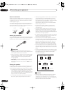
• For a second recorder, use the
DVR/
VCR2
outputs.
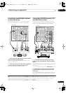
3 If the device can output digital audio, connect an
optical-type
1
digital audio output from the recorder to
the DIGITAL 2 (DVR/VCR1) input.
Use an optical cable for the connection.
2
• For a second recorder, use the
DIGITAL 3
(
DVR/
VCR2
)
inputs.
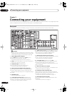
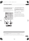
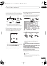
Using the component video jacks
Component video should give superior picture quality
when compared to composite or S-video. You can also
take advantage of progressive scan video (if your source
and TV are both compatible), which delivers a very stable,
flicker-free picture. See the manuals that came with your
TV and source component to check whether they are
compatible with progressive-scan video.
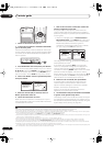
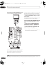
1 Connect the component video outputs of your
source to a set of ASSIGNABLE COMPONENT VIDEO
inputs.
Connect using a three-way component video cable.
• Since they are assignable, it doesn’t matter which
component video inputs you use for which source.
After connecting everything, you’ll need to assign the
component video inputs—see
The Input Setup menu
on page 63.
2 Connect the COMPONENT VIDEO OUT jacks to the
component video inputs on your TV or monitor.
Use a three-way component video cable.
Note
1• In order to record, you must connect the analog audio cables (the digital connection is for playback only).
• If your video component doesn’t have a digital audio output, you can skip this step.
2 If your recorder only has a coaxial digital output, you can connect it to one of the coaxial inputs on this receiver using a coaxial digital audio cable. When
you set up the receiver you’ll need to tell the receiver which input you connected the recorder to (see also
The Input Setup menu
on page 63).
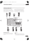
VSX-84TXSi
MULTI-ROOM
& SOURCE
/
REC SEL
ROOM3
(
ZONE3
)
OUT1
OUT2
USB
AUDIO
IN
S400
(
AUDIO
)
S400
(
DVD/LD
)
(
TV
)
FM UNBAL 75 Ω
AM LOOP
MONITOR
OUT
OUT
CD
CD-R/
TAP E
DVD/
LD
TV
SAT
VIDEO /
GAME1
OUT
DVR/
VCR 1
DVR/
VCR 2
OUT
IN
IN
VIDEO
VIDEO
AUDIO
S
-
VIDEO
IN
IN
IN
FR FL
SUB W.
CENTE
R
MULTI CH
IN
SUR-
ROUND
SURROUND
BACK
CONTROL
OUT
PHONO
IN
IN
IN
IN
Y
P
B
P
R
Y
P
B
P
R
Y
P
B
P
R
Y
P
B
P
R
DIGITAL
COMPONENT VIDEO
ASSIGNABLE
ASSIGNA-
BLE
ASSIGNABLE
OUT
OUT
ANTENNA
MULTI-ROOM & SOURCE
AUDIO
IN
IN1
IN2
IN1
1
12 V TRIGGER
2
MONITOR
OUT
MULTI-ROOM
& SOURCE
ROOM2
ROOM2
(
ZONE2
)
ROOM2
(
ZONE2
)
MAIN ROOM
(
ZONE1
)
(
ZONE2
)
IN2
(
DC OUT 12V TOTAL 50 mA MAX
)
IN3
IN4
OUT
(
SAT
)
(
DVR/
VCR 1
)
1
IN
2
(
DVR/
VCR 2
)
IN
3
(
DVD/
LD
)
IN
1
(
CD
)
IN
IN
XM
2
IN
2
IN
OUT
1
IN
1
IN
2
IN
1
IN
2
R
L
HDMI
MULTI-ROOM
& SOURCE
IR
IN
3
(
CD-R
)
IN
4
4
1
21
21
31
R L
L
L
L
R
R
R
Y
P
B
P
R
COMPONENT
VIDEO
Y
P
B
P
R
COMPONENT
VIDEO
2
1
TV
DVD player
VSX_84TXSi.book.fm 14 ページ 2006年3月13日 月曜日 午前11時54分