


Other connections
08
52
En
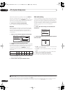
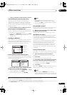
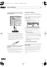
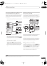
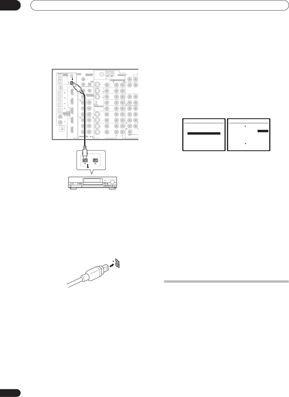
1 Use an i.LINK cable to connect one of the i.LINK
connectors on this receiver to an i.LINK connector on
your i.LINK component.
• The arrow on the cable connector body should be
lined up with the arrow (to the left of the connector)
on the receiver for correct alignment. The i.LINK
cable should be inserted straight into the connector
so that it snaps easily into place. If not connected
properly the receiver will not be able to recognize any
connected components. Note that the i.LINK cable is
fragile and can be broken easily if too much force is
used when connecting.
2 Assign the i.LINK component to the input you want,
then make any necessary output settings on the
component.
See
The Input Setup menu
on page 63 to assign the
component to an input function on this receiver. Follow
the operating instructions that came with the component
to make any necessary output settings.
• You can connect several components together using
i.LINK. See
Creating an i.LINK network
below.
Checking the i.LINK inputs
If you have several i.LINK-equipped components and
have assigned them to input functions in
The Input Setup
menu
on page 63, you can confirm the settings you made
below.
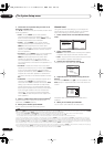
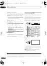
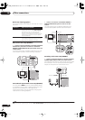
1 Select ‘i.LINK Check’ from the Other Setup menu
and press ENTER.
See
The Other Setup menu
on page 64 for more on
navigating this menu screen.
• If no i.LINK-equipped components are connected
i.LINK Check
cannot be selected.
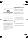
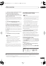
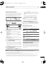
2 Scroll through the list to confirm your settings.
When a number of i.LINK-equipped components are
connected to your receiver, the i.LINK-equipped
component you are looking for might be listed on
additional display screens.
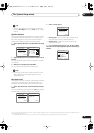
•
i.LINK
is displayed after unassigned device names
(e.g.
DV-79AVi [i.LINK]
).
• If a connected devices cannot output (playback) a
source using the i.LINK connection,
[- - - -]
is
displayed after the input device name (e.g.
DV-79AVi
[- - - -]
). Non-compatible devices cannot be assigned
to inputs.
• When the cables for an assigned input device
become loose or the power is cut to the device, an
asterisk (
*
) appears before the device name (e.g.
*DV-79AVi [CD]
).
3 When you're finished, press
RETURN
.
You will return to the Other Setup menu.
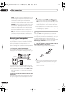
About i.LINK
i.LINK is a trademark name for IEEE1394, a high-speed
interface for digital audio, video and other data found on
personal computers, digital camcorders, and other kinds
of audio and audio/visual equipment. A single i.LINK
connector can both send and receive data at the same
time, so only one cable is required to connect compo-
nents for two-way communication.
“i.LINK” and the “i.LINK” logo are trademarks of Sony
Corporation.
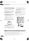
MULTI-ROOM
& SOURCE
/
REC SEL
ROOM3
(
ZONE3
)
OUT1
OUT2
USB
AUDIO
IN
S400
(
AUDIO
)
S400
(
DVD/LD
)
(
TV
)
FM UNBAL 75 Ω
AM LOOP
MONITOR
OUT
OUT
CD
CD-R/
TAP E
DVD/
LD
TV
SAT
VIDEO /
GAME1
OUT
DVR/
VCR 1
DVR/
VCR 2
OUT
IN
IN
VIDEO
VIDEO
AUDIO
S
-
VIDEO
IN
IN
IN
FR FL
SUB W.
CENTE
R
MULTI CH
IN
SUR-
ROUND
SURROUND
BACK
CONTROL
OUT
PHONO
IN
IN
IN
IN
Y
P
B
P
R
Y
P
B
P
R
Y
P
B
P
R
Y
P
B
P
R
DIGITAL
COMPONENT VIDEO
ASSIGNABLE
ASSIGNA-
BLE
ASSIGNABLE
OUT
OUT
ANTENNA
MULTI-ROOM & SOURCE
AUDIO
IN
IN1
IN2
IN1
1
12 V TRIGGER
2
MONITOR
OUT
MULTI-ROOM
& SOURCE
ROOM2
ROOM2
(
ZONE2
)
ROOM2
(
ZONE2
)
MAIN ROOM
(
ZONE1
)
(
ZONE2
)
IN2
(
DC OUT 12V TOTAL 50 mA MAX
)
IN3
IN4
OUT
(
SAT
)
(
DVR/
VCR 1
)
1
IN
2
(
DVR/
VCR 2
)
IN
3
(
DVD/
LD
)
IN
1
(
CD
)
IN
IN
XM
2
IN
2
IN
OUT
1
IN
1
IN
2
IN
1
IN
2
R
L
HDMI
MULTI-ROOM
& SOURCE
IR
IN
3
(
CD-R
)
IN
4
4
1
21
21
31
R L
L
L
L
R
R
R
(AUDIO)
S400
i.LINK-equipped component
VSX-84TXSi
7.Other Setup
:Return
a.Multi Room Setup
b.SR+ Setup
c.OSD Adjustment
d.i.LINK Check
7d.i.LINK Check (1/2)
( End )
* DVD-Audio5 : TV
1 DVD-Audio1 : DVD
2 DVD-Audio2 : DVR
3 DVD-Audio3 : i.LINK
4 DVD-Audio4 : i.LINK
5 VSX-59TXi : ----
( Next )
:Return
VSX_84TXSi.book.fm 52 ページ 2006年3月13日 月曜日 午前11時54分