


Other connections
08
51
En
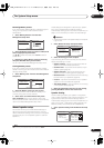
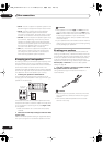
2 Use an HDMI cable to connect the HDMI OUT
interconnect on this receiver to an HDMI interconnect
on a HDMI-compatible monitor.
• The arrow on the cable connector body should be
facing right for correct alignment with the connector
on the player.
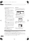
3 Use the INPUT SELECT button to select the HDMI
input you’ve connected to (for example, HDMI 2).
You can also use the front panel
INPUT SELECTOR
dial.
• Set the HDMI parameter in
Setting the AV options
on
page 66 to
THROUGH
if you want to hear HDMI
audio output from your TV or plasma display (no
sound will be heard from this receiver).
• If the video signal does not appear on your TV or
plasma display, try adjusting the resolution settings
on your component or display. Note that some
components (such as video game units) have
resolutions that may not be converted. In this case,
use an analog video connection.
• You can’t hear HDMI audio through this receiver’s
digital out jacks.
About HDMI
HDMI (High Definition Multimedia Interface) supports
both video and audio on a single digital connection for
use with DVD players, DTV, set-top boxes, and other AV
devices. HDMI was developed to provide the technolo-
gies of High Bandwidth Digital Content Protection
(HDCP) as well as Digital Visual Interface (DVI) in one
specification. HDCP is used to protect digital content
transmitted and received by DVI-compliant displays.
HDMI has the capability to support standard, enhanced,
or high-definition video plus standard to multi-channel
surround-sound audio. HDMI features include uncom-
pressed digital video, a bandwidth of up to 2.2 gigabytes
per second (with HDTV signals), one connector (instead
of several cables and connectors), and communication
between the AV source and AV devices such as DTVs.
HDMI, the logo and High-Definition Multi-
media Interface are trademarks or registered trademarks of
HDMI licensing LLC.
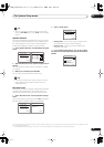
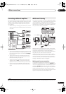
Using the i.LINK interface
VSX-84TXSi only
If you have a component with an i.LINK connector, you
can connect it to this receiver using an i.LINK cable.
Since the i.LINK interface does not transmit video
signals, the video signal of i.LINK-connected compo-
nents must be connected with other cables (see
Connecting your equipment
on page 10 for more on
making video connections). If you’ve already hooked up
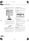
the video signal from the component, assign the i.LINK
input to the input function to which you’ve connected the
video signals (see
The Input Setup menu
on page 63). See
Checking the i.LINK inputs
below to confirm your i.LINK
settings.
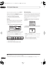
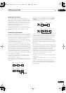
The two i.LINK connectors on the rear of your receiver are
4-pin connectors. Use a 4-pin, S400 i.LINK cable to
connect i.LINK-equipped components.
Caution
• If your i.LINK connector comes into contact with
metallic parts of the receiver other than the i.LINK
terminal, an electrical short may occur. Some cables
have metal parts that may touch the unit when
connected. Please take care to use a suitable i.LINK
cable only.
Important
• Please use 4-pin, S400 cables less than 3.5 meters
long. Although longer ones are available, they may
not work reliably.
• There may be cases where the PQLS/rate control
function and/or the i.LINK audio does not work prop-
erly even when connected to i.LINK Audio-compat-
ible equipment.
• Do not connect/disconnect i.LINK cables or switch
on/off any components connected using i.LINK when
the receiver is on.
VSX_84TXSi.book.fm 51 ページ 2006年3月13日 月曜日 午前11時54分