


Pelco Manual C550M-E (8/97) 5
4. The contact pins supplied with the mating con-
nector are the “crimp” type which may also
be soldered if you so desired (item 4).
5. After crimping or soldering the contact pins
to the conductors, push them into the proper
holes in the connector until they snap in place.
Note: Contacts cannot be removed from the con-
nector without the use of the appropriate AMP ex-
traction tool which is available from PELCO.
6. Slide part A of the cable clamp toward the con-
nector and screw the parts together. Attach part
B (item 1) onto part A and connect both parts
with the screws provided.
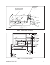
7. Connect the cable assembly to the unit and
seat the connector by twisting the locking col-
lar until it snaps into position (see Figure 5
and Figure 10).
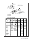
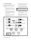
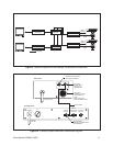
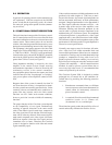
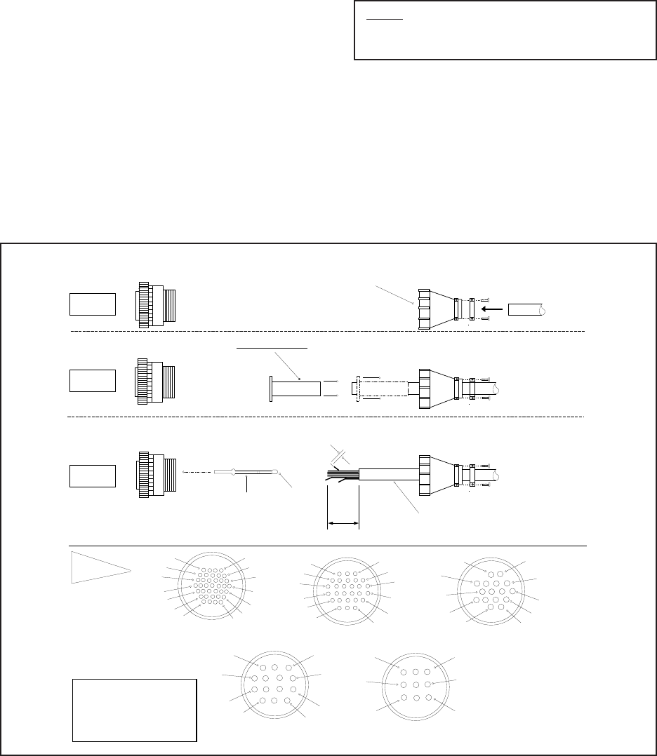
4.2 CONNECTOR ASSEMBLY
Installation and/or testing will require you to assemble
the connector parts provided. Fabricate the intercon-
necting cable according to the following steps (refer-
ence Figure 4).
1. Slide part A of the cable clamp (item 1) over
the end of the cable (item 1, part C) with the
threaded end of the cable clamp facing the con-
nector (item 5).
2. If the cable has a diameter less than 1/2 inch
(1.3 cm), slide the rubber boot (item 2) over
the end of the cable and pull through the cable
clamp to so that the boot encases the cable and
forms a good seal.
3. Strip back the cable jacket approximately 1-
1/4 inches (3.2 cm) and separate the individual
conductors (item 3).
Figure 4. Connector Assembly
STEPS 3-7
1
5
10
16
23
29
34
9
15
22
28
33
37
4
FRONT VIEW
37-PIN CONNECTOR
1
FRONT VIEW
3
7
11
14
15
16
10
6
2
16-PIN CONNECTOR
1
4
FRONT VIEW
9-PIN CONNECTOR
3
6
79
1
4
FRONT VIEW
14-PIN CONNECTOR
3
7
8
11
12
14
1
9
15
4
FRONT VIEW
28-PIN CONNECTOR
21
26
3
8
14
20
25
28
FLEXIBLE RUBBER BOOT
CRIMP
WIRE
CRIMP
INSULATION
STRIP 1"
STRIP 1/8"
OUTSIDE
JACKET
OF CABLE
4
3
2
1
A B C
5 **
5
5 1
A B
C
1
A B
C
threaded end of
cable clamp
STEP 1
STEP 2
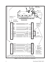
THE MOST COMMONLY USED
CONNECTOR PIN-OUT CONFIG-
URATIONS ARE SHOWN HERE.
REFERENCE THE CONNECTOR
DRAWING APPLICABLE TO
YOUR SITUATION.
**
ITEM 5 DETAIL