


2 Pelco Manual C550M-E (8/97)
NOTE: This manual applies to those Coaxitron
systems using either PCB1500529 REV J or
PCB1500529 REV K boards. PCB board draw-
ings were done from the REV J board perspective;
however, differences between the two boards that
affect function or operation are clearly pointed out.
2.0 SCOPE
The information contained within this manual covers
the installation and operation of the Coaxitron System
2000 (transmitter control and receiver).
Installation should be in accordance with all applicable
local and national electric codes, utilizing approved
materials only.
Please thoroughly familiarize yourself with the infor-
mation in this manual prior to installation and operation.
3.0 DESCRIPTION
The Coaxitron System 2000 control system provides up
to 16 remote control functions without the need for
control cables other than for a dedicated video cable for
the normal transmission of a remote camera signal to the
local monitoring and control position. The Coaxitron
Control System lends itself to application in situations
where short-to-medium distances are involved and where
equalization of cable losses is not required.
Typically, these functions are:
1. Pan Left 9. Iris Open
2. Pan Right 10. Iris Close
3. Tilt Up 11. Camera Power On/Off
4. Tilt Down 12. Auto/Manual Scan
5. Zoom In 13. AUX 1 (Manual Iris)
6. Zoom Out 14. AUX 2 (Auto Iris)
7. Focus Near 15. AUX 3
8. Focus Far 16. AUX 4
Functions 1 through 10, 15 and 16 are momentary; that
is , they are only actuated while the associated control
switch located on the Coaxitron transmitter or front
panel is operated. Functions 11, 12, 13 and 14 are
latching; that is, camera power, auto scan, and auto/
manual iris are latching functions and remain on until
turned off. The latching iris function is not dedicated,
and with proper interfacing, it can be used for some
other latching function. Alternately, AUX 1, 2, 3 and 4
may be used as momentary functions to control such
things as lights or gates with proper external interfacing.
Up to ten functions can be operated simultaneously.
Functions 11 through 16 must be used individually;
although any one of these functions may be used simul-
taneously with functions 1 through 10.
Coaxitron System 2000 is an improved version of the
original Coaxitron. Improvements include the follow-
ing features:
1. When used with an AI700 Auto Iris Servo, three
latching functions rather than two are available: (a)
auto scan, (b) camera power and (c) auto/manual
iris.
2. When used with a CX900TLC Local Test Board
Plug-in Module, manual control of functions from
the receiver location plus the ability to check for the
valid reception of a given command from the
transmitter.
3. Pan/tilt, zoom lens and camera power control are
included on the main (video and logic) receiver
board, which eliminates malfunctions due to
miswiring or broken wires.
Coaxitron System 2000 provides the following stan-
dard functions on a single circuit board and chassis with
integral power supply:
1. Pan/Tilt (24 VAC or 120 VAC as ordered from the
factory)
2. Zoom Lens — Zoom, iris, and focus with adjust-
able speed (speed not remote controllable)
3. Camera power (24 VAC or 120 VAC as ordered
from the factory)
4. An open collector transistor output (latching) in-
tended for use in manual override of an automatic
iris control.
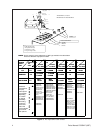
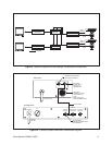
4.0 INSTALLATION
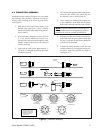
Coaxitron System 2000 installation includes the con-
nection of all coaxial cable to the proper connectors,
depending on your system configuration. Various con-
nector assembly pin-out geometries are shown in Figure
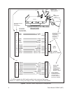
4. Connector location and pin assignments are illus-
trated in Figure 5.
For optional auxiliary functions, consult the factory to
make the proper connections between the receiver, pan/
tilt and camera/enclosure.
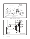
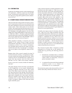
4.1 RECEIVER POWER INPUT
MODIFICATIONS
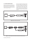
4.1.1 24 VAC Input Conversion
The CX9024RX series receivers can be converted to
operate with a 24 VAC input. If desired (see Figure 2).
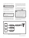
Please contact factory for more information. For AC
input and fuse values, refered to Figure 3.