


8 Pelco Manual C550M-E (8/97)
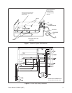
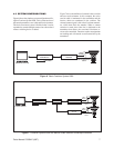
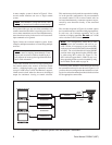
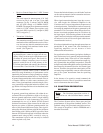
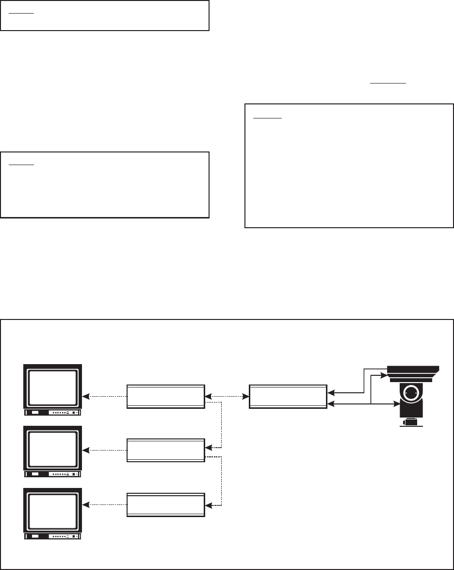
A more complex system is shown in Figure 8. Here,
several control locations can serve a single camera
system.
Note: All transmitters, except the last one, must
be looping (unterminated) rather than terminating.
In a system of this type, any one of the transmitters can
assume control because there is no priority provision. If
two or more transmitters are activated simultaneously,
error detection circuitry in the receiver will cause mul-
tiple commands to be ignored.
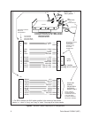
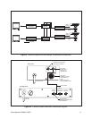
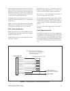
Figure 9 shows an even more complex system. In this
example, multiple transmitters are controlling multiple
receivers.
Note: All but the last transmitter and associated
switcher must be looping (unterminated). Trans-
mitters and associated switchers should be physi-
cally adjacent to insure against signal deterioration
due to cable mismatch.
Video cables from the receivers are looped through the
first control station to the second. At the first control
station, a bridging-looping type sequential switcher
(except VA500 series) is used. The Monitor 2 output is
a hard contact switch, otherwise known as the bridged
output for continuous viewing or control selection.
Figure 8. Coaxitron System 2000 with Multiple Transmitters
This monitor may also be used for sequential switching.
As in the previous configuration, any one transmitter
can assume control. If two or more control units are
activated simultaneously, erroneous responses are pre-
vented by error detection circuitry in the associated
receiver.
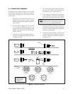
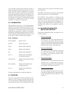
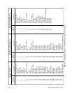
The switchers depicted in Figure 10 are hard contact
devices and do not have isolation or bridging amplifiers.
In each case, the Coaxitron transmitter acts as the
isolation or bridging amplifier. Do not use VA500
series switchers with Coaxitron systems.
Note: For configurations where RG59 cable
length between the transmitter and receiver ex-
ceeds 750 feet, it is necessary to reset switch SW1
on the receiver board (PCB1500529) from SHORT
to LONG. The switch should be left in the SHORT
position when using shorter lengths of RG59 cable
or when using RG11 cable (see Figure 5). For
RG11 cable, the upper limit is 1800 ft. In any case,
these operating distances can be extended by using
the EA2000. See the table on page 26.
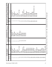
Coaxitron System 2000 basic interconnections between
the transmitter and receiver are shown in Figure 10. If
you have chosen a configuration that includes a switch-
ing device, refer to the manual provided with the switcher
for the appropriate connections.
COAXITRON
TRANSMITTER
COAXITRON
RECEIVER
VIDEO
SIGNAL
MULTI-CONDUCTOR
CABLE
COAXITRON
TRANSMITTER
COAXITRON
TRANSMITTER
TERMINATE MONITOR
TERMINATE MONITOR
TERMINATE MONITOR
UNTERMINATED
TRANSMITTER
UNTERMINATED
TRANSMITTER