


Pelco Manual C550M-E (8/97) 23
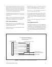
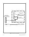
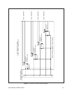
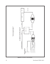
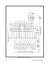
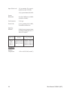
Figure 21. CX900TLC Test Module and Wiring Schematic
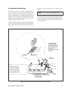
6.0 TROUBLESHOOTING GUIDELINES
If you experience operating problems with either the
receiver or transmitter, first check all fuses and voltage
readings to make sure they are in working order. The
CX900TLC can be utilized to verify receiver functions
and accessories are operational.
There is little that can be done without the aid of an
oscilloscope. We recommend you contact your local
dealer or our Customer Service Department for assis-
tance.
Copies of the Coaxitron System 2000 Maintenance
Manual (document number C550SM) are available on
request.
U1
1N914
1
2
8
3
R1
100K
+10
GND
ACTIVE
14 15
U1
CD4049
U1
U1
U1
U1
R2
820
LED 1
12
10
6
4
11
9
7
5
AUTO
SCAN
CAM
ON
AUX 4
AUTO
IRIS
AUX 2
IRIS
CLOSE
FOCUS
NEAR
ZOOM
WIDE
DOWN
RIGHT
LEFT
UP
ZOOM
TELE
FOCUS
FAR
IRIS
OPEN
AUX 1
MAN
IRIS
AUX 3
CAM
OFF
MAN
SCAN
S1
S2
S3
S4
S5
S6
S7
S8
S9
S10
S11
S12
S13
S14
S15
S16
S17
S18
S19
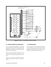
RIGHT
DOWN
ZOOM
WIDE
FOCUS
NEAR
IRIS
CLOSE
AUX 2
AUTO
IRIS
AUX 4
CAM ON
AUTO
SCAN
LEFT
UP
ZOOM
TELE
FOCUS
FAR
IRIS
OPEN
AUX 1/MAN IRIS
AUX 3
CAM
OFF
MAN
SCAN
20
21
22
1
2
3
4
5
6
7
8
9
10
11
12
13
14
15
16
17
18
19
20
21
22
U1
R1
CR1
R2
CR2
LED
INDICATOR
7
8
1
2
3
4
5
6
9
10
11
12
14
15
16
17
18
19
13
INTERCONNECT TO RECEIVER
BOARD PCB1500529
P3
7.0 MAINTENANCE
The Coaxitron System 2000 is engineered to provide
years of reliable service. The Coaxitron System 2000
has very few operator serviceable parts and we recom-
mend that system components be serviced by a trained
technician or returned to the factory for repair.