


Pelco Manual C550M-E (8/97) 11
As an example, assume that the operator switches to
manual iris control and proceeds to open the iris exces-
sively. The result can be a complete loss of control.
Within 20 to 40 seconds, camera power is automatically
removed (assuming this feature exists) and auto iris is
reinstated. Thus, distortion products are eliminated if
the camera power function is incorporated in the system
or reduced to a tolerable level if only the AUTO/
MANUAL iris function is incorporated.
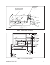
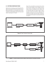
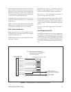
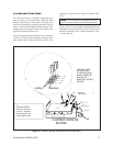
5.2 TRANSMITTER
The transmitter is housed in a 1-3/4" high enclosure,
supplied as a desk top unit (rack mount available). Three
video connectors (J6, J7, J8) are located on the rear rail
(see Figure 10). J8 allows the user to loop the camera
signal from one transmitter to another, or to terminate
the signal by installing the appropriate resistor. Connec-
tor J7 accepts the camera signal from the receiver, and
J6 provides an output for monitoring equipment.
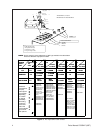
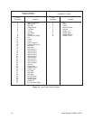
5.2.1 Controls
Power ON/OFF Rocker switch
Pan/Tilt 8-position joystick
Zoom Paddle switch Tele/Wide
Focus Paddle switch Near/Far
Iris Paddle switch Open/Close
Aux 1,2 Paddle switch Auto/Manual
Iris (latching function)
Camera Power Paddle switch On/Off (latching
function)
Pan Auto/Man Paddle switch Manual/Auto
(latching function)*
Aux 3, 4 Paddle switch (momentary
functions)*
*External requirements are needed for operation
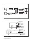
5.3 RECEIVER
The receiver and control function assemblies are con-
tained in a “J-Box” housing. One end of the J-Box has
two video connectors (input and output) and CPC-type
control cable connector. Provision is made on this same
surface for entry of AC power line (120/230/24 VAC).
(See Figure 10.)
The INPUT video connector accepts the signal from the
camera and provides a 75 ohm termination.
The OUTPUT video connector is connected to the
transmitter input connector (J7) via a dedicated and
continuous coaxial cable. Proper termination of this
cable is vital to the operation of the equipment. Al-
though loop-through connections in this cable are per-
missible, power splitter or line amplifiers cannot be
tolerated.
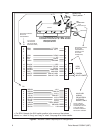
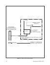
5.4 RECEIVER/TRANSMITTER
INPUTS AND OUTPUTS
The Receiver/Transmitter inputs and outputs are de-
scribed as follows:
• Receiver Video Input
Normally, this is the video signal from the cam-
era serviced by the receiver. The receiver pro-
vides a 75 ohm cable termination and an isolation
amplifier to prevent the control pulse train from
being fed to the camera. (See Figure 10.)
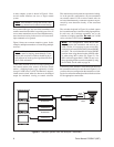
• Receiver Video Output
This output is fed to the transmitter video input
(J7) via 75 ohm coaxial cable. Active elements
or “splitters” in this cable run cannot be toler-
ated. (See Figure 9.)
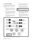
• Receiver Power Input
All Coaxitron receivers may be powered by 24/
120/230 VAC as ordered from the factory.
The AC power input for 24 VAC operation must
be changed as described in Section 4.1.
• Receiver Control Output
All control signals from the receiver are avail-
able from an AMP Series CPC output connector,
except for optional auxiliary functions. (See
Figure 10.)